Visual Land Prestige Elite 9Q LCD Screen Replacement
ID: 65709
Description: In this guide you will be shown how to...
Steps:
- Using the large plastic opening tool, start along a side of the device and apply light pressure in the seam between the top and bottom outer covers.
- Maneuver the smaller plastic opening tool at the spot of the large opening tool and slowly slide along the edge.
- You should feel each plastic connections begin to loosen.
- Move tool around each connection, and continue around the device until all connections have been loosened.
- The user risks damaging the connections if they slide across to fast.
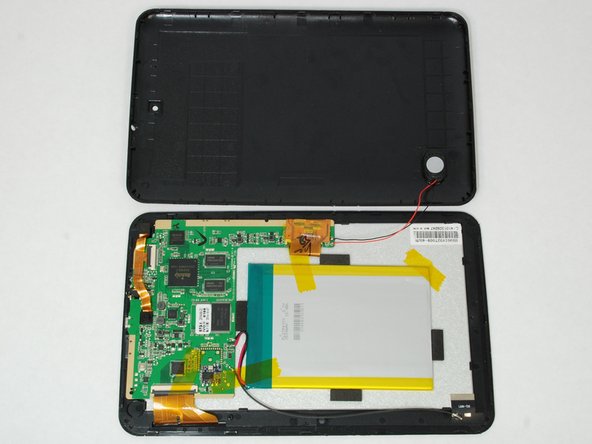
- Once all connections have been loosened and using a soft surface, place the device onto its screen and lift gently on the outer casing.
- Open the casing and lay as shown keeping the speaker wires loose.
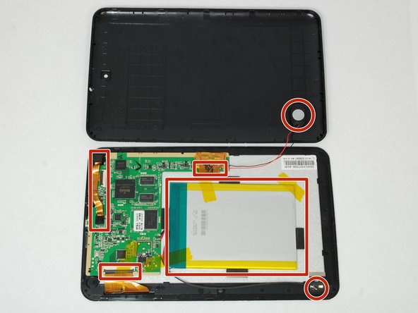
- The highlighted areas represent connections to disassemble.
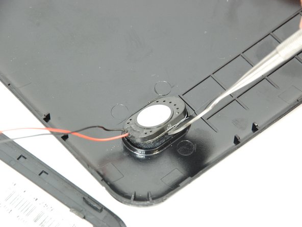
- Using hook tweezers and a spudger, gently remove the glued speaker away from the casing.
- The tweezers can damage the speaker.
- The speaker is still connected to the motherboard with wire, so be cautious during this process.
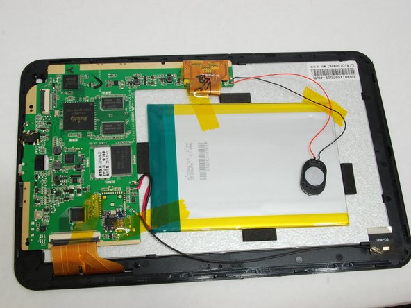
- Using wide-tip tweezers, gently remove the three pieces of tape attached to battery
- The battery is still connected to the circuit board, and do not damage the tape as it holds the battery to the rest of the device.
- Next remove the WiFi module from the bottom of the device. This is simply pealed off.
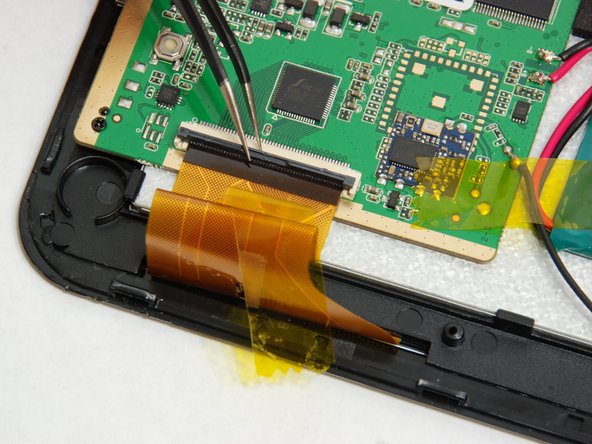
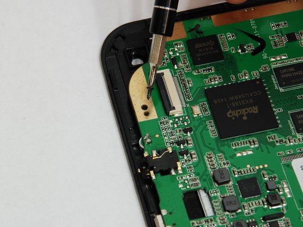
- Gently remove tape from circuit board, and disconnect the ZIF (zero insertion force) connectors for the front panel and LCD screen.
- Use tweezers to lift up the black hinged lock on top of the ZIF connector.
- Use pointed hook tweezers to gently lift up front facing camera by grabbing the padding on back of camera.
- Located on corner of tablet
- Do not grab camera lens, tweezers may damage lens.
- Use pointed hook tweezers to gently remove rear facing camera by grabbing the corner of camera casing.
- Located above charger jack.
- Do not grab camera lens, tweezers will damage camera lens.
- Use pointed hook tweezers to gently flip up hinged ZIF connector.
- After ZIF connector is flipped up, remove camera module.
- These are the three screws holding the circuit board.
- Use J00 or PH00 to remove the three screws.
- Make space in work area, and remove battery, circuit board, speaker, and wifi module as one from the LCD screen and front glass.
- Handle carefully because battery speaker and wifi module are only connected by soldered connections.
- Shown are all the clips that hold the LCD screen to the front glass.
- Start in the corner and pull back one of the black tabs. At the same time try to get under the screen with the tweezers.
- Once one side is pulled up the rest should come off relatively easily.
- After detaching front glass from LCD Screen, lay LCD screen down on white styrofoam side and this is what it will look like.
- Do not place screen down on black side to prevent damaging screen
- After removing LCD screen this is what the front glass component will look like.
- At this point a better assessment can be made of whether the LCD screen is bad or the front glass is cracked.