Full method - HP Touchsmart IQ506 CMOS Battery Replacement
ID: 66721
Description: Do you need to change the CMOS battery in your...
Steps:
- Due to the EET missing several components present in the Pro Tech Go and only being $20 cheaper, the EET has been removed. The EET will work for this guide as-is, but if you are shopping for a new toolkit to complete this guide, the Pro Tech Go (new or refurbished, refurbished is ~$32 cheaper), or Pro Tech ($79 new/~$59.95 refurb) is the current recommended toolkit for this guide.
- If you are interested in a refurbished kit stock levels change frequently but can be found here.
- Unplug the system from the power brick.
- READ: I did not get the original keyboard with my system and the receiver mine came with was broken. Since the HP OEM keyboard is NLA, I installed a USB hub to use another keyboard.
- To remove the back cover from the system, the keyboard receiver must be removed. To do this, pull the receiver by the notch to release it. Once you do this, it should come out of the internal USB port to free the back cover.
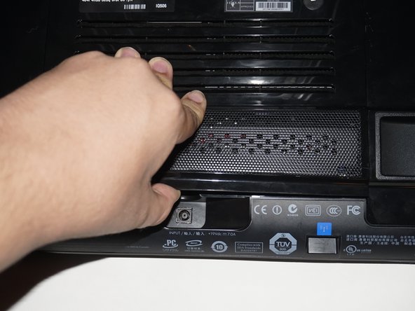
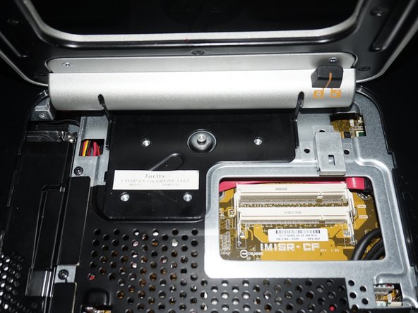
- Remove the screw on the RAM door. Once you remove the screw, unclip the door.
- THIS STEP ONLY APPLIES FOR LEGACY iFixit 54-BIT DRIVER KIT USERS.
- When usjng the legacy driver handle, the top hinge screws can be difficult to get to. If you have the legacy 54-bit iFixit driver kit, lock the stand upright and slide it under the stand from the rear to access the top screws. This should be less of an issue with a standalone driver or modern driver kits like the 64-bit/Manta kit.
- It may be easier to remove the top screws from the stand first due to their placement.
- Remove the stand from the system. Use a Phillips #1 screwdriver to loosen the 4 screws. A standalone driver may work best for this step.
- Remove the 3 screws in the I/O bay of the system.
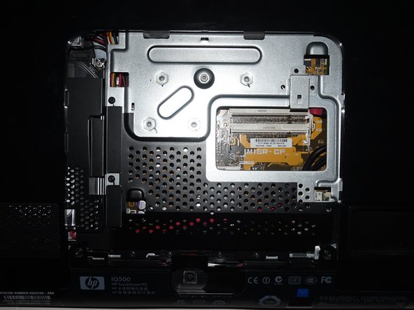
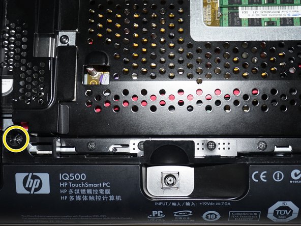
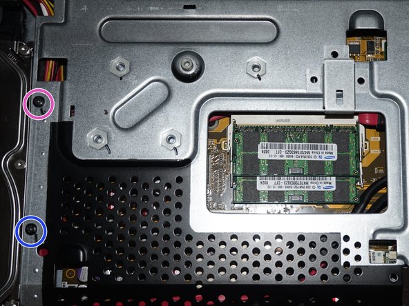
- Remove the 2 screws from under the RAM panel. Note: My system is missing a screw, but it is marked accordingly. Yoy may or may not need to keep this in mind.
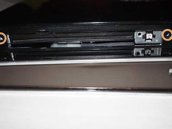
- Remove the 2 screws from under the ODD cover. Tip: If you are having trouble with this cover, use a spudger or plastic pry tool to remove it.
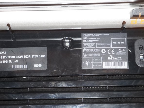
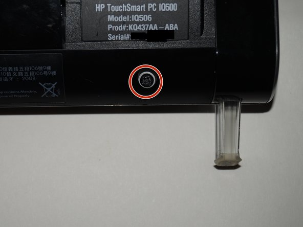
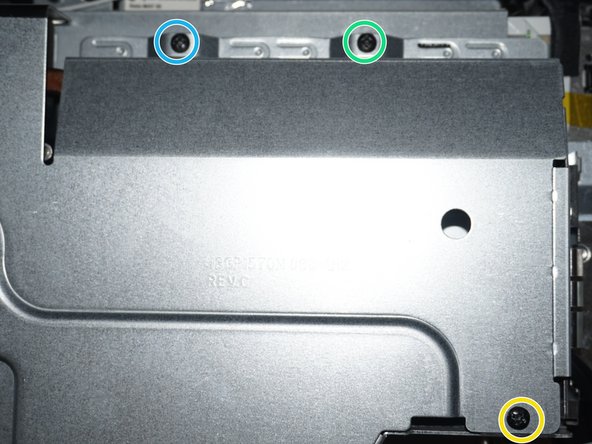
- NOTE: ONE SCREW NOT SHOWN DUE TO PHOTO LIMIT. Remove the 2 screws above the model number palte.
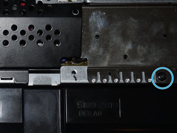
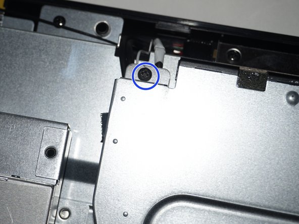
- Remove the 2 screws by the feet on the system chassis.
- If you have difficulty removing the back of the system, a spudger may help you release the tabs.
- Remove the back from the system. The quickest way to do this is to start from the bottom and then unsnap the sides.
- The metal EMI shield over the power jack has to be removed to pull the motherboard shield off. This must be replaced when reassembling the system.
- Remove the 7 screws to reveal the motherboard and other major components. Use a Phillips #1 screwdriver to do this.
- Remove the 6 remaining screws from the motherboard shield. Use the same Phillips #1 screwdriver as you used the first time.
- If you want to track when you replaced the battery, put a mark on the battery with the month and year so you know when it was replaced. If you cannot write on the battery, putting a hidden note under the memory panel is also an option.
- Optional: Put a note on the RAM door out of sight or write when the battery was replaced on the new battery.
- Push the tab on the battery in and then remove it. Put the new battery in the reverse way of removal. Once this is done, write when the battery was replaced (Example: 5/16) on the battery.