Replacing the Sony Cyber-shot DSC-P10 Built-in Flash
ID: 6867
Description: Is your Cyber-shot camera's flash no longer...
Steps:
- Unscrew the 4 screws on top of camera.
- Unscrew the 4 screws on bottom of camera.
- When all 8 have been unscrewed, remove front and back cover from camera.
- Find the marked piece located on the right side of the camera and gently pull to remove.
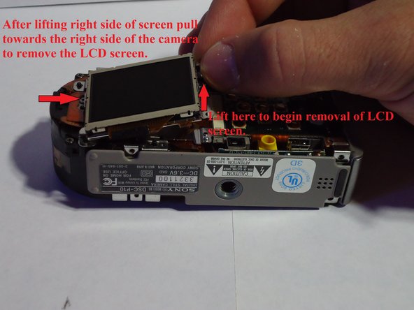
- Begin by removing the small piece of black foam located at the top right of the LCD screen. (Image 1)
- Remove the screw located directly underneath the foam. (Image 1)
- Lift the right side of the LCD screen up and to the right, pulling it out of the camera. (Image 2)
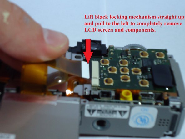
- There will be two ribbon circuits remaining.
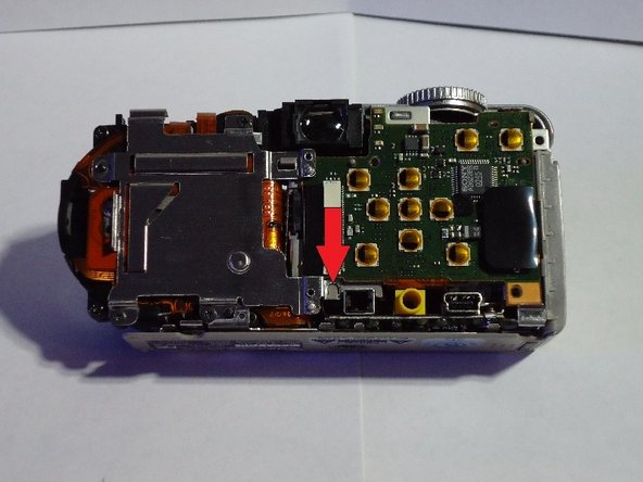
- Lift the black locking mechanism up and pull to the left. This will completely detach the LCD screen and its components. (Image 3)
- Remove the three screws securing the metal backing. (Image 1)
- Push down the marked plastic piece on the top right, then lift the backing up to release the top half. (Image 2)
- To free the backing completely, pull it downwards to loosen it from the marked catch on the lower right. (Image 3)
- Lift the metal backing up and off of the camera.
- Disconnect the two ribbon circuits on the front of the camera.
- The camera should now be in two parts. Set the lens half off to the side and continue working with the side containing the flash.
- Lift the left side of the bottom panel towards the top of the camera.
- Then pull the panel down and away from the camera.
- Remove the screw from the upper right corner.
- Carefully work the marked ribbon circuit on the left back and forth to free it from the plastic retainer. (Image 1)
- Lift the black locking mechanism up and gently pull the ribbon circuit to detach. (Image 2)
- Upon completion of this step, the lower circuit board should be attached in one place and be freely hanging as shown.
- Remove upper left ribbon circuit by lifting the black locking flap and gently pulling out.
- Remove the lower right ribbon circuit by gently pulling out.
- Remove the lower left screw.
- Remove the three screws securing the rear circuit board.
- Lift up on the left side of the circuit board and gently pull to the left to dislodge.
- Gently lift the rear circuit board away from the camera.
- The film behind it is attached, but not securely. Keep the circuit board and the film together to avoid damage.
- Rotate the circuit board 180 degrees so that it is directly below the camera.
- Now gently remove the front circuit board and rotate both the rear and front circuit boards 180 degrees so that they are directly above the camera. (Image 2)
- Lift the marked black locking mechanism up and gently pull the ribbon circuit free.
- Use tweezers to remove the wires from the circuit board. Grasp the white plastic plug and pull gently until free.
- Note: The marked wires are connected on the side facing your work surface.
- Using the tip of your tweezers, press on the latching mechanisms one at a time to free the flash housing piece.
- Gently pull up on the flashing housing piece to remove.
- Note: If you are struggling to free the piece, you may have to wiggle it back and forth to free the circuit board located on its underside.
- Remove the marked tape to release the top half.
- The built-in flash is in the half with the circuit board, as shown in Image 2.
- You are now ready to replace this piece with your new built-in flash.