HP Photosmart c3180 Feed Roller Assembly Replacement
ID: 6990
Description: The feed roller assembly is a critical...
Steps:
- Before disassembling your printer, be sure that the printer has been unplugged to avoid any risk of injury.
- Rotate the printer 90 degrees counter clockwise so that the side panel next to control panel is facing you.
- Remove the two T10 12mm Torx screws from the left side panel.
- Firmly pull the the back of the side panel until it separates from the body of the printer.
- Rotate the side panel upwards while pulling it towards yourself to remove the panel.
- Rotate the printer 90 degrees clockwise.
- Grasp the paper tray and rotate it down.
- Insert your fingers into the slot in the printer door and pull to rotate the gate down.
- Rotate the printer 90 degrees clockwise.
- Remove the two T10 12 mm Torx screws.
- Grasp both sides of the side panel and pull it forward to remove the panel.
- Rotate the printer 90 degrees counter clockwise.
- Lift the scanner lid to expose the scanner glass.
- Remove the two T10 12 mm Torx screws.
- Do not attempt to lift the top panel off the printer yet because it is still connected to the printer body by a cable.
- Rotate the printer 90 degrees counter clockwise.
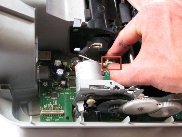
- Inside the printer is a small white tab. Press it inward with a spudger until a pop is heard.
- Remove the front panel by grasping its front and pulling away from the printer.
- Rotate the printer 90 degrees clockwise.
- Remove the cable connecting the top panel of the printer to the power button assembly.
- Carefully lift the top panel of the printer away from the printer body.
- Set aside the top panel of the printer.
- Remove the two T10 12 mm Torx screws from the top front of the printer
- Rotate the Printer 90 degrees counter clockwise.
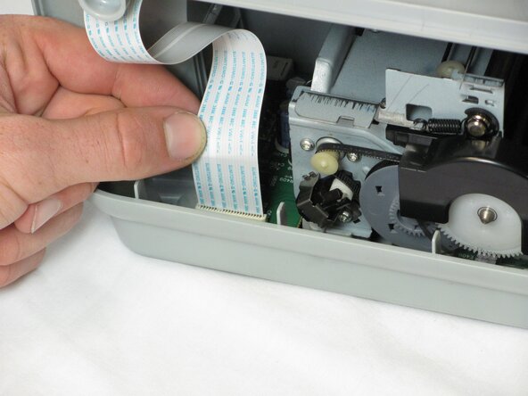
- Remove the scanner cable from the main circuit board.
- Grasp the bottom of the cable and pull straight up. Do not wiggle it from side to side or twist it as this can damage the connection.
- Rotate the printer 90 degrees clockwise.
- Using both hands, lift the scanner tray from the body of the printer.
- Remove the power button circuit board from the support frame by pinching the left side, and pulling forward and to the left simultaneously.
- Push up on the tab holding the secondary control circuit board with the spudger and pull it forward to remove it.
- Be careful not to pull too hard on the cable connecting the power button control circuit board and the secondary control circuit board to the main circuit board
- Remove the two T10 12 mm Torx screws.
- Lift the support frame off of the printer body with both hands.
- Remove the printer door and paper tray by putting them in the closed position and not laying flat then rotating them upwards lift the left side up.
- Remove both of the ink cartridges by grabbing the front of the ink cartridge and pulling down.
- Make sure that the printer carriage is pushed all the way to the right.
- Remove the T10 6 mm Torx screw on the left side of the track assembly.
- Remove the T10 12 mm Torx screw on the left side of the track assembly.
- Gently push the ink cartridge carriage to the left side of the printer.
- Remove the two T10 12 mm Torx screws.
- Remove the two T10 6 mm Torx screws.
- Rotate the printer 90 degrees counter clockwise.
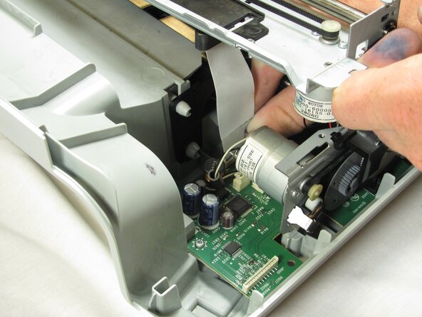
- Remove the cable connecting the ink cartridge carriage to the main circuit board.
- Pull straight up to free the cable from the main circuit board. Do not twist or wiggle the cable as doing so can damage it.
- You may need to lift the carriage up with one hand in order to reach the cable with the free hand as shown.
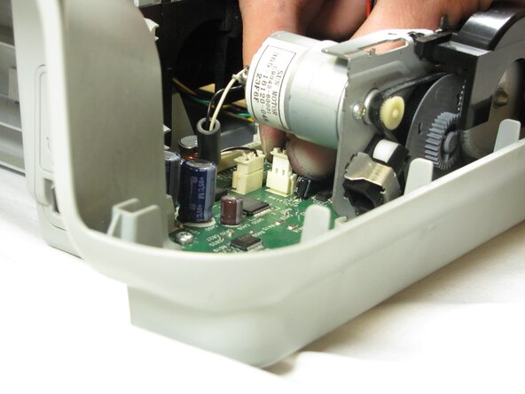
- Carefully remove the connector holding the drive motor wires to the main circuit board.
- Slide the ink cartridge carriage all the way to the right side of the printer.
- Using both hands, carefully lift the ink cartridge track off of the main body of the printer.
- Set aside the ink cartridge carriage.
- Remove the three T10 12mm Torx screws holding the paper guide to the printer body.
- Lift the paper guide directly up to remove it and set it aside.
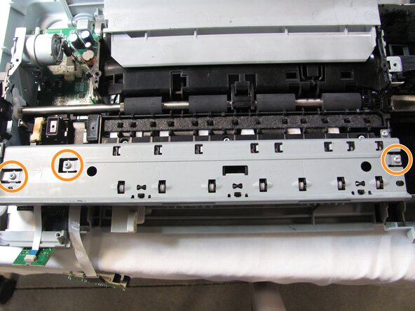
- Remove the five T10 12mm Torx screws from the roller holder.
- 5th screw is located in deeper crevice.
- Remove the plastic gear cover by pulling it away from the printer body and lifting it up.
- Remove the metal tab by rotating it away from the body of the printer and pulling up.
- Remove the brush by grasping it firmly by the base and lift straight up.
- Remove the pad holder by lifting it straight up.
- Remove the connector holding the feed roller motor to the logic board by pulling it strait up
- Remove the T10 12mm Torx screw on the roller panel.
- Disconnect the page sensor from the logic board by pulling straight up on the connector.
- Rotate the printer 180 degrees and turn it up on to the front side, so that the back of the printer is facing up and the bottom facing you.
- Be careful because the feed roller assembly is now loose, but it is still attached to the main body of the printer.
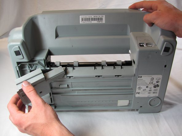
- Push in the tab on the left side of the back panel and pull outward to remove the back panel.
- Tilt the printer up until the bottom of the printer can be seen.
- Remove the T10 12mm Torx screw from the bottom panel.
- Grasp the top edge of the bottom panel and pull to remove it.
- Remove the black plastic cross member from the bottom of the printer.
- Turn the printer back down so that it is sitting on the bottom panel and rotate the printer 180 degrees.
- Remove the printer head cleaner by lifting the front of the printer head cleaner above the track and slide it forward.
- This is an extremely difficult step. It can take quite a bit of force to lift the printer head cleaner above the track and it is easy to slip and hurt yourself.
- This step can be performed with out rotating the printer, but we have rotated the printer for clarity.
- Grasp the left side of the feed roller assembly and pull towards the front of the printer and up to free the metal tab from the slot.
- Lift the feed roller assembly straight up to remove it.