Macintosh PowerBook 165c Motherboard Replacement
ID: 7023
Description: This guide will show you how to replace the...
Steps:
- Orient the computer so the battery is facing you.
- Slide the gray plastic battery cover to the right.
- Pull the battery toward yourself until it is fully detached.
- Orient the computer right side up with the rear facing you.
- Open the Input/Output (I/O) door.
- Carefully bend the door into an arch until one of the pins releases from its slot.
- Once one of the pins is free, remove the I/O door from the computer.
- Orient the computer with the bottom facing up and rear facing you. You should be able to read the Macintosh label in this position.
- Use a T8 torx screwdriver to remove the 6.8mm long screw above and to the right of the modem jack.
- Twist counter clockwise to remove the screw.
- Use a T10 torx screwdriver to remove the four, 18mm long screws from the lower case.
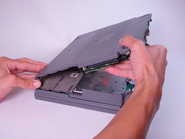
- Place your hands on the lower case, just above the I/O panel, and slowly lift the lower case a few inches above the main body of the computer.
- Release the large, gray interconnect ribbon cable just behind the I/O panel.
- Caution: Lower case cannot be fully removed until two plastic clips in the front corners are released. See the following step for details.
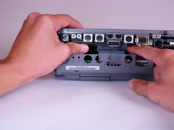
- Place your thumb on the upper case, inside the empty battery slot, and your index finger near your thumb on the left side of the lower case.
- Pinch your thumb and index finger towards each other to release the clip. Without releasing pressure on the pinch grip, use your index finger to push the lower case upwards.
- Lift the lower case to remove it.
- Orient the computer so the ports are facing you.
- Locate the Modem Card on the lower case.
- Use a T8 torx screwdriver to remove the two, 7.7mm long screws from the two corners.
- The modem card is an optional component on the Macintosh 165c, and may not be included in all devices.
- Lift the modem card directly upward until it releases from the connector.
- If the modem card is difficult to remove, gently jostle it back and forth as you lift up.
- Locate and lift ram card directly up until connector releases.
- Move the card back and forth gently if the connector does not release immediately.
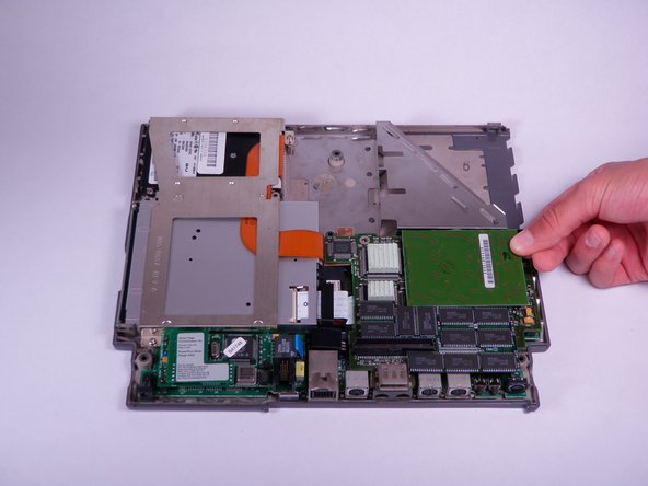
- Locate and lift the PSRAM expansion card vertically until connector releases.
- If the PSRAM expansion card is difficult to remove, gently jostle it back and forth as you lift up.
- The PSRAM expansion card is an optional component, and may not be included in all devices.
- Use T8 torx screwdriver to remove four, 7.7mm long screws from the perimeter of the daughterboard.
- Life the daughterboard directly up to remove it from the connector.
- If the daughterboard does not easily release from the connector, gently jostle it back and forth as you lift up.
- Remove the three cylindrical silver spacers placed on top of the motherboard.
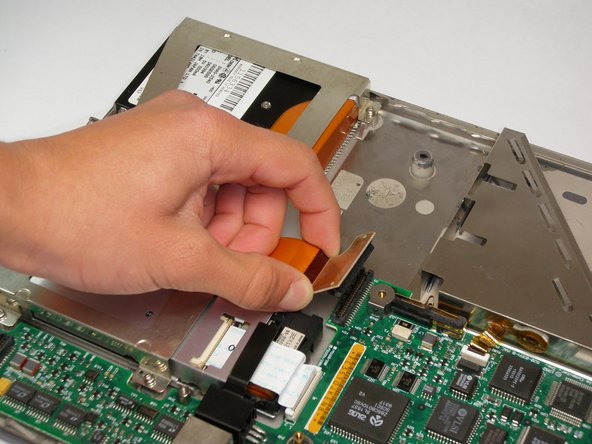
- Lift up on the orange connector attached to the hard drive until it releases from the motherboard.
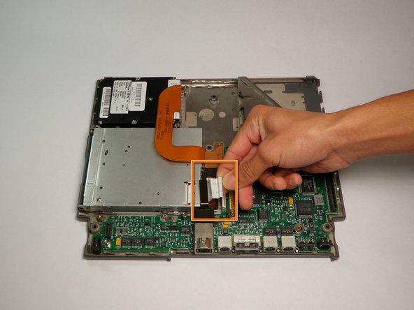
- Open the white tab fastener by lifting up on both sides.
- Remove the white ribbon cable by gently pulling it away from the opened tab fastener.
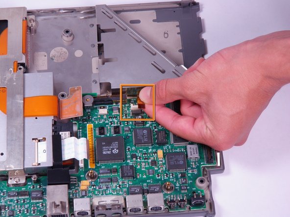
- Open the white lock out tab located at the top of the motherboard.
- Remove the black and orange ribbon cable by gently pulling it away from the opened tab fastener.
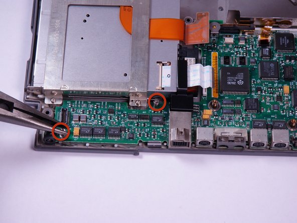
- Use needle nose pliers to remove the two, 5mm inch wide and 10.8mm long hex bolts from the lower left side of the motherboard.
- To remove bolts with pliers, twist counter clockwise.
- Lift up on the motherboard to remove it.