Dell Inspiron 14z-5423 Fan Replacement
ID: 72571
Description: The fan in this laptop prevents the computer...
Steps:
- Close the display and turn over the computer.
- Make sure your device is powered down and unplugged before beginning the replacement.
- Use a J0 bit tipped screwdriver to unscrew the one 6 mm Phillips screw on the RAM cover.
- Lightly lift the RAM cover up and at an angle, away from the computer.
- Use your fingers to carefully pull the securing clips on the RAM away from each other.
- The RAM should pop up when the clips are released.
- Remove the popped up RAM by pulling it away from the connection.
- If it does not pop up pry it out in a steady and straight direction.
- Slide the CD/DVD drive on the side of the laptop out using your fingers.
- Using a J0 bit screwdriver, unscrew the one 2 mm Phillips screw.
- You only need to unscrew this screw if you are using this as a prerequisite guide.
- Lift the plastic yellow flap on the system board.
- Use the J0 Bit screwdriver to remove the one 6 mm Phillips screw in center of the system board that is connected to the keyboard.
- Flip over the computer and open the display.
- Insert a spudger next to the plastic indents located at the top of the keyboard and gently pry to release the securing clips.
- Lift the keyboard off of the computer.
- Be careful not to tear the ribbon that attaches the back of the keyboard to the computer when lifting it.
- Flip the keyboard over onto the palm-rest assembly.
- Flip the little black securing bar near the base of the ribbon with a spudger to release the ribbon from the computer.
- Close the display and turn over the computer.
- Remove all 7 rubber screw caps with tweezers.
- Use a J0 Bit tipped screwdriver unscrew the seven 6 mm Phillips screws on the back casing of the laptop.
- Flip the computer over and open the display.
- Pull on the blue tabs to disconnect the palm rest assembly from the computer.
- Use J0 Bit screwdriver to remove all four 6 mm Phillips screws.
- Gently wedge the nylon spudger underneath the palm-rest assembly to release the latches.
- Continue this process on all sides of the computer edges until the assembly pulls off.
- Remove the palm rest assembly.
- If you have difficulty lifting up the assembly, you might not have taken out all 7 screws on the bottom of the computer.
- Use a J0 Bit screwdriver to remove the two 6 mm Phillips screws securing the battery located near the bottom of the laptop.
- Lift the tiny black tab and pull the battery out at a slight angle.
- Lift up the bottom of the hard drive which is located at the bottom of the laptop.
- Gently pull the drive out at an angle using your fingers.
- Using a J0 bit tipped screwdriver, remove the four 3 mm black screws on both sides of the hard drive bracket.
- Slide the hard drive out of the bracket.
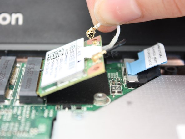
- Locate the wireless mini card at the top of the laptop.
- It is next to the place where the optics drive used to be.
- Using a J0 tipped screwdriver, remove the 4 mm Phillips head screw.
- Gently, unlatch the black and white wires from the wireless mini card.
- At an angle, slide out the wireless mini card.
- Gently pull the the blue ribbon upwards to disconnect the computer from the motherboard.
- Using a plastic opening tool, gently detach the coin cell battery from the foam glue.
- The coin cell battery is underneath the optical drive.
- Using a J0 tipped screwdriver remove the 6 mm Phillips head screw located at the center of the laptop on the motherboard.
- Remove motherboard at an upward angle.
- The coin cell battery and fan will be removed with the motherboard.
- Flip the motherboard over.
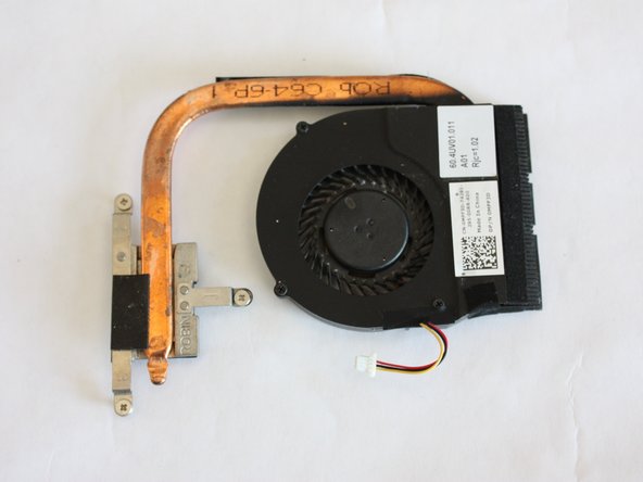
- Locate the red and yellow wires attached to the fan and gently detach them from the motherboard.
- Using a J0 tipped screwdriver remove the three 5 mm Phillips head screws that attach fan to the motherboard.
- The fan base is labeled 1, 2, 3. Make sure you unscrew the screws in this order.
- The screws are attached to the fan and will fully unscrew.
- Remove the fan from the motherboard by lifting upwards.