LG CU400 Charging Port Replacement
ID: 72830
Description: This guide will walk you through the steps to...
Steps:
- Push the button labeled 'PUSH' on the rear cover.
- Slide the rear cover towards you.
- To remove the battery, grasp the top front edge of the battery and pull the battery away from the phone.
- When installing the new battery, have the metal contacts of the phone match up with the metal contacts of the battery.
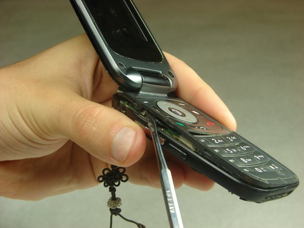
- Remove the sim card by sliding the card out from under the retainer using either your fingers or a spudger.
- Remove the rubber covers in the highlighted locations using a metal spudger.
- Remove the six 3mm #000 flat Phillips head screws from the back of the phone using a Phillips #000 Screwdriver.
- Remove the headphone jack cover with your finger or metal spudger.
- Insert the metal spudger between the keypad assembly and back cover assembly and pry the two assemblies apart.
- Pry gently as to not break the plastic clips that hold the two assemblies together.
- Work your way around the perimeter of the phone with the metal spudger to separate the two assemblies.
- Once you have worked your way around the perimeter of the phone, you will have access to the components in the bottom half assembly.
- You should notice that the number pad is loose and can simply be taken out of the open phone casing.
- Using the spudger, start to gently pry the motherboard from the back of the phone and work your way around the perimeter of the motherboard.
- There are copper ribbon cables connected to each side of the motherboard leading to the buttons for volume control and the camera that need slid out of the phone casing as the motherboard is being removed.
- There are three in total, but do not remove the top one from the phone casing yet.
- Once the motherboard is not locked in place it will still be attached to the back phone casing by two wires, red and black, twisted together.
- Use tweezers to grab the black piece that these wires are attached to and simply pull it off the motherboard.
- You may need to flip the phone over so that the screen is facing down. Feel free to move the keypad assembly to the closed position for this step.
- Remove the display ribbon cable from the back of the motherboard using tweezers.
- Make sure to lift it so that you are pulling the entire thing off at once and not pulling off the flat piece at an angle.
- Use tweezers to remove the top ribbon cable, mentioned in step 11, from the hinge area.
- Grasp either side of the motherboard and gently lift it away from the phone casing.
- The motherboard should be completely free of the phone casing, and you should have what is shown in the pictures.
- Locate the 6 locations that need to be desoldered.
- Using a desoldering braid and a soldering iron, remove the soldered connections. Use the website " How To Solder and Desolder Connections " for more information on soldering.
- When attaching the new charging port, use the solder and not the desoldering braid to make the conection.
- You will need to coat the boxed area with flux liquid and then heat it with a heat gun while gently prying the charging port with the micro soldering tweezers. Use the video https://www.youtube.com/watch?v=jGZKsuaJ... for more information on micro soldering.
- Make sure to watch the video to see how to micro solder the new charging port on.