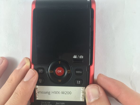
Samsung HMX-W200 Camera Lens Replacement
ID: 72958
Description: For the user to remove the camera lens of the...
Steps:
- Remove the 5.00mm screw on the right of the LCD display towards the bottom of the device by using a Phillips #00 screwdriver.
- Use the plastic opening tool to separate and remove the bottom red casing. Do this by, pushing the tool into the seam and prying up the red casing as you move along the edges.
- Make sure to separate all the corners before removing the red casing.
- Using the plastic opening tool, separate and pull away the red casing on the right of the LCD screen.
- Make sure to separate all the corners before removing the red casing.
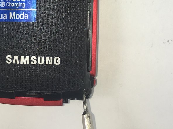
- To access the HDMI slot, move slider towards the bottom of the casing on the other side of the camcorder. The lid casing will lift up upon doing so.
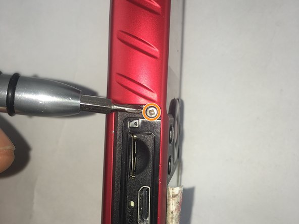
- After accessing the HDMI slot you will find a 5.00mm screw. Using a Phillips #00 screwdriver, remove the screw.
- Using the plastic opening tool, separate and pull away the red casing to the left of the LCD screen.
- Make sure to separate all the corners before removing the red casing.
- Remove the six 5.00mm screws by using a Phillips #00 screwdriver.
- Lift the two plastic tabs on the left side of the LCD screen and the single one on the right side on the black casing to open the device.
- Separate the front and back casing.
- Once inside the device, find the half that contains the motherboard of the device.
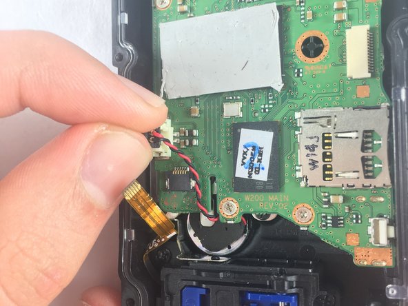
- Use precision tweezers to gently pull out the USB connection from the motherboard.
- Remove the audio connector from the motherboard (red and black cables).
- Using the plastic opening tool, lift the connectors from all sides before pulling it with your fingers.
- Do not pull off the connectors by the cables. This could damage the connection from the speaker to the motherboard.
- Use precision tweezers to remove the connector joining the LCD and the motherboard.
- Remove the six 2.00mm screws with Phillips #00 screwdriver.
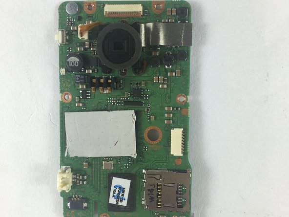
- Lift motherboard from top left side and pull away gently.
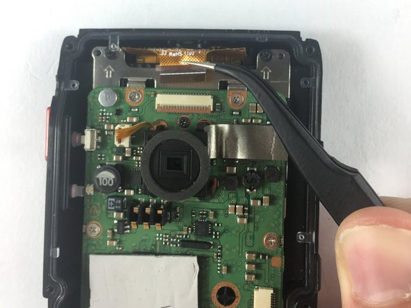
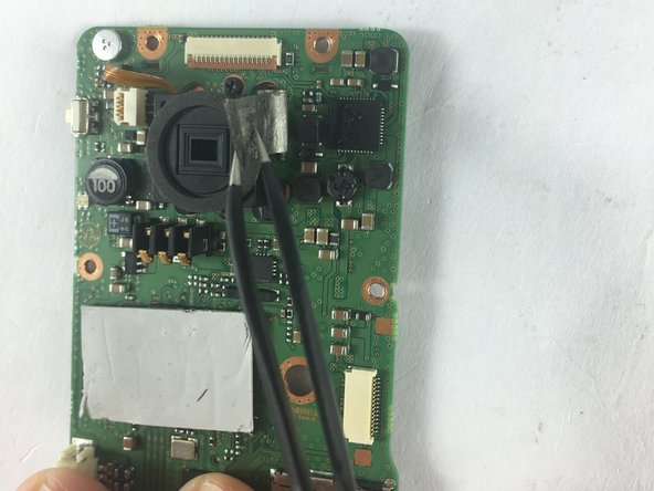
- Use the precision tweezers, to gently pull and remove the connector connecting lens and motherboard.
- Using the precision tweezers, lift silver heat sync tape from motherboard.
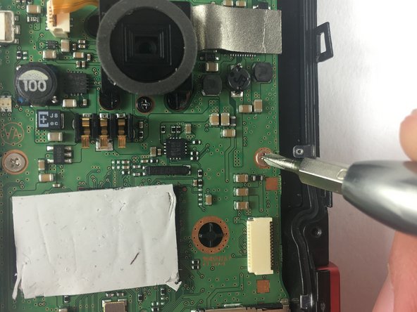
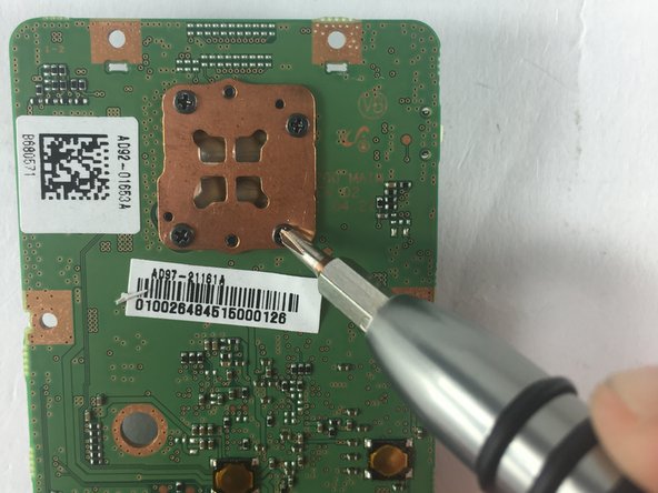
- Turn the motherboard over.
- Use Phillips #00 screwdriver to unscrew four 4mm screws holding the camera lens to the motherboard.
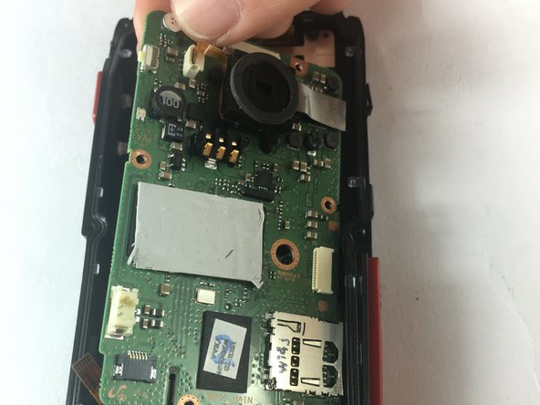
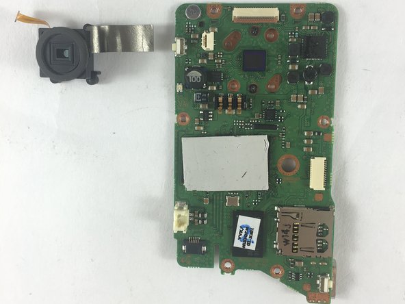
- Gently grab the lens with your fingers and pull it away from the motherboard.
- Camera lens should easily come off the motherboard when the last screw is loose.