Verizon Ellipsis 7 Front Facing Camera Replacement
ID: 74622
Description: This guide illustrates how to correctly replace...
Steps:
- Hold down the power button until the screen goes black to turn off the device.
- Remove the SIM card from the device to prevent damage.
- To remove the SIM card, open the SIM card cover on the side of the device.
- Push SIM card in and pull it out after hearing a click.
- Take off the back panel.
- Pry open the back cover carefully with a plastic opening tool.
- Use the opening tool to disconnect the cover completely. Do not attempt to pry the back cover off with your hands.
- Be sure to pry open all sides of the device. Attempting to take off the back cover when part of it is attached may snap the cover.
- Remove the charging (micro-USB) port.
- Unscrew the indicated screws using the Phillips #00 screwdriver.
- The screws shown in the picture are the more common 4.76 mm.
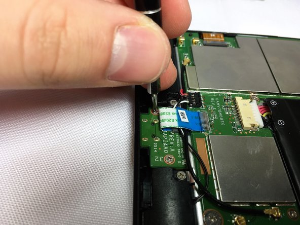
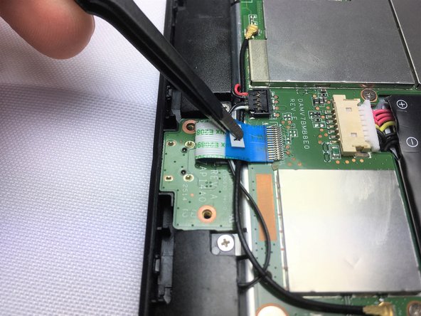
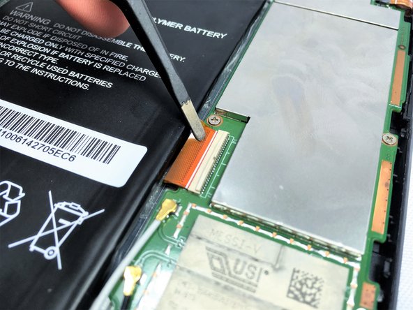
- Disconnect the ribbon cable connecting the charging port board to the motherboard using tweezers.
- Use the tweezers to grab the sides of black, plastic connector. Do not grab from the wires or try to wedge it out from the bottom.
- Be extremely careful when disconnecting the ribbon cable. It is very delicate.
- Remove the charging port board from the phone using tweezers.
- Place the replacement charging port into the phone.
- Be cautious when replacing the ribbon cable onto the new charging port board.
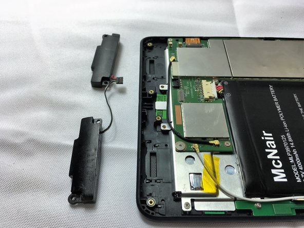
- Remove 2 screws from each speaker, 4 screws in total, using a Phillips #00 screwdriver.
- The screws shown in the picture are the more common 4.76 mm.
- Using tweezers carefully lift the connector up to disconnect it from the motherboard.
- Using tweezers carefully pull the speakers up and out of device.
- Use tweezers to carefully disconnect the power cable bundle from the motherboard.
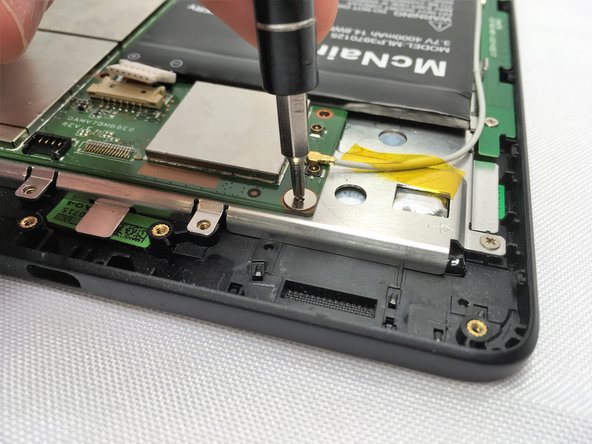
- Remove the 10 screws from the motherboard using a Phillips #0 screwdriver.
- The screws shown in the first picture is the more common 4.76 mm.
- The screw shown in the second picture is shorter than the rest of the screws: 3.175 mm.
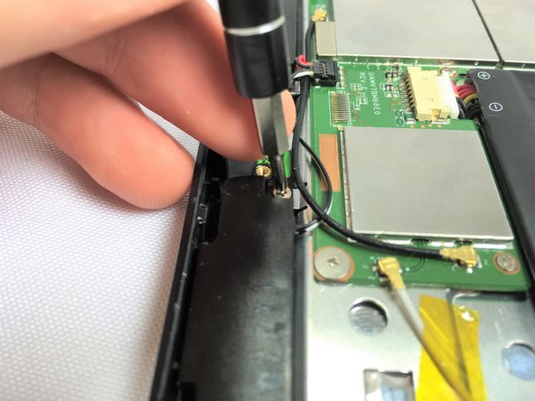
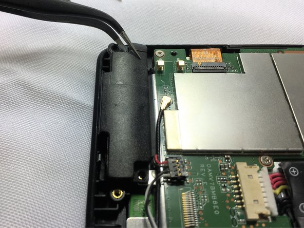
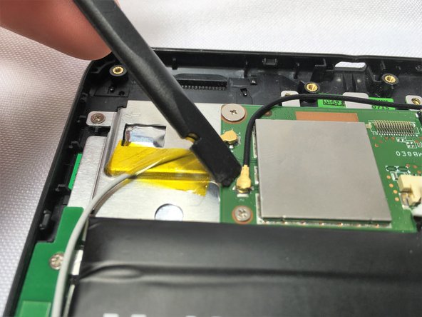
- Using a spudger, remove the 5 antenna cable connectors from the motherboard.
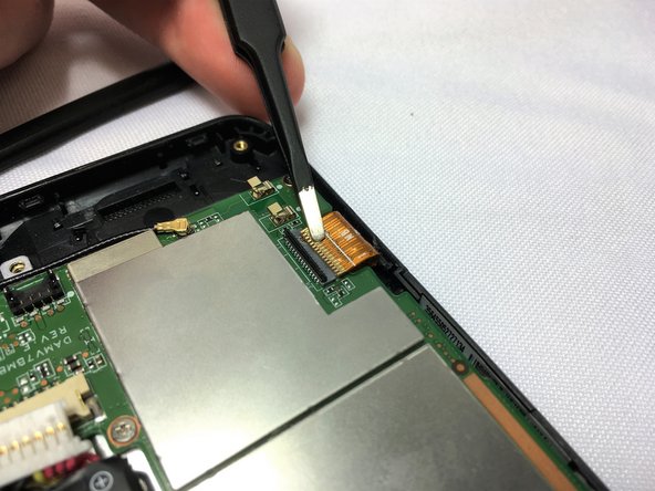
- Disconnect the two ZIF connectors that are connected to the motherboard with the spudger. Lift up the metal part of the connector and pull it off of its port
- Once disconnected from the port, pull the metal part away from its connector carefully with the tweezers.
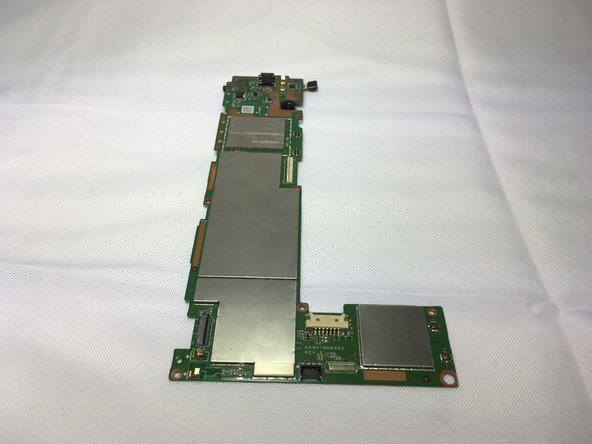
- When all the connectors have been disconnected, you can gently lift the motherboard from the device.
- Make sure the press lift connector is disconnected using the spudger, then carefully flip the motherboard over.
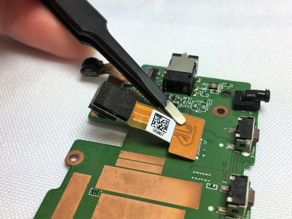
- Disconnect the camera in the middle of the board using tweezers.