Dell Inspiron B130 Motherboard Replacement
ID: 74729
Description: Replacing a motherboard is a complex repair...
Steps:
- First, make sure your computer is turned off.
- Remove the battery by flipping the two switches under the battery and pulling it out
- Push the tab from the battery, downwards to unlock the battery.
- The tab should be in the position next to the unlocked indicator.
- Now, push the other tab (the one right under the battery) from right to left.
- Now the battery will be loose; lift the battery up and out of the computer.
- Remove the 8mm screw
- Use the plastic opening tool to push out the disk drive.
- Pull the disk drive out with the opposite hand.
- You can now remove the disk drive.
- This particular computer is missing its hard drive.
- Remove the two screws.
- Remove the plastic cover by lifting from the groove as indicated.
- Remove the hard drive from the computer by lifting up and out.
- Put down the computer and open up the screen.
- There is a long piece of plastic underneath the screen that you will have to remove.
- When you pry the plastic plate off, be careful and pry gently so you do not crack the plastic.
- Insert the plastic opening tool into the little slot.
- Lift up gently and remove the plastic cover.
- Remove the two 4mm screws at the top of the keyboard.
- The keyboard is now loose but don't pull it out just yet. It is still connected underneath. Be gentle when lifting keyboard so you do not damage this connection.
- Lift keyboard up slightly and you will see the keyboard connection.
- This black tab has to be lifted up to remove the keyboard.
- Put your finger underneath the tab and pull back gently as indicated.
- You can now remove the keyboard.
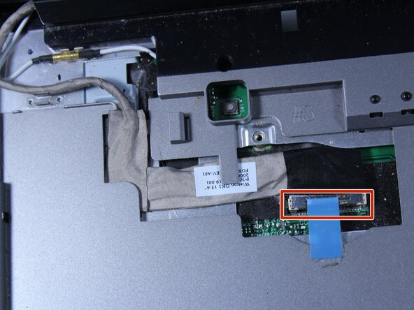
- Detach the blue display connector.
- Detach the connector by pulling the two ends straight apart.
- Avoid twisting or pulling at an angle to prevent damage.
- Use a Phillips #1 screwdriver to remove two 6 mm screws.
- Close the computer and flip it over so that the back is facing up.
- Remove the two 6mm screws that are behind each of the screen's pivot points using a Phillips #1 screwdriver.
- Open up the screen and now it can be lifted up and off of the computer.
- Remove the 6 mm screw.
- Lift the plastic cover off.
- Loosen the 4 screws.
- These screws stay connected to the heat sink.
- Remove the heat sink from the computer.
- Use a flat head screwdriver to turn the screw one quarter turn into the unlock position.
- Remove the CPU.
- Remove the three 6mm screws.
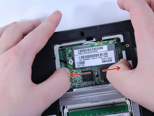
- Lift the plastic cover off to reveal the RAM and the Wireless.
- To remove the RAM, push outward against the metal brackets.
- The first RAM will pop up so you can just pull it right out.
- Repeat the first step again to remove the second RAM chip.
- Installation is the reverse of removal.
- To remove the wireless chip, push outward on its two metal brackets.
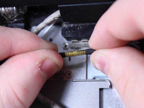
- Do not remove the chip just yet, the wire that connects this chip must first be removed.
- To remove the wire, hold the wireless chip firmly and pull the connection straight up off of the chip.
- Use a Phillips #0 screwdriver to remove the twelve 8mm screws from the bottom of the laptop.
- The picture shows everything still installed in the computer. At this point, the CPU, RAM, battery, hard drive and wireless chip should all be removed.
- Turn the laptop over so that the keyboard side is facing up.
- Remove the two 4mm screws positioned just below where the screen would be using a Phillips #0 screwdriver.
- Remove the five remaining 6mm screws.
- Disconnect the two connections carefully.
- Do not pull by the wires! This can damage the connection. Use tweezers to grab by the white plastic piece and push outward.
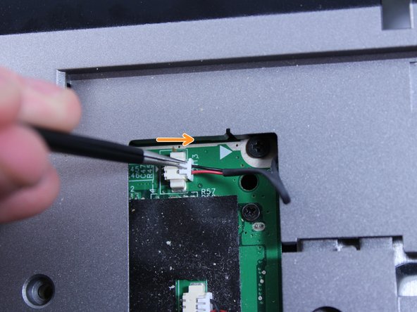
- Disconnect this connection before proceeding.
- Use tweezers to grab the small black connector and pull it straight back carefully. Avoid pulling on the wire directly, as this may cause damage to the connection.
- You can now disconnect this wire.
- Lift and remove the entire cover/frame from the top of the motherboard. Gently pull up to detach it without using excessive force
- Remove the motherboard by pulling it upward and sliding it to the right. Be careful not to damage any remaining connectors or components. If the motherboard feels stuck, double-check that all screws and cables have been disconnected.