LeapFrog LeapPad 2 Separate Motherboard and Screen Assembly
ID: 74747
Description: In the event that you're having trouble with...
Steps:
- Turn the tablet so the back is visible.
- One at a time, remove the battery covers by sliding them towards the sides and away from the center of the device.
- Remove the AA batteries from both battery compartments of the device.
- Use a Phillips #1 screwdriver to remove the following screws from the device:
- Four 7.0mm Phillips screws
- Three 6.0mm Phillips screws
- Two 10.0mm Phillips screws
- These two screws are behind the barcode decal on the bottom of the device. Expose the screws by puncturing, cutting, or peeling the barcode decal.
- Use a small plastic opening tool to begin separating the colored front cover from the white rear cover of the device.
- With one hand on the front cover and one hand on the rear cover, start from the bottom of the device and begin pulling the pieces apart.
- The most stubborn tabs holding the front and rear together are along the top edge of the tablet around the game cartridge slot. This will most likely be the last area that separates, and it may require a moderate amount of force.
- Once only the top edge remains connected, simultaneously pull the rear cover backwards away from the front cover and upwards towards the top of the device. This should release the last remaining tabs holding the pieces together.
- Use a Phillips #1 screwdriver to remove two 5.5mm screws from the plastic speaker holder.
- The rear camera is shown removed in these images, but its removal is optional for most tasks.
- Remove the plastic speaker holder from the device.
- Use a Phillips #1 screwdriver to remove the following screws:
- One 5.5mm Phillips screw holding the screen assembly.
- Two 8.0mm Phillips screws holding the motherboard.
- Two 6.0mm Phillips screws holding the game cartridge slot.
- One of these screws also holds a black plastic bracket for the front camera, and the bracket is loose once the screw is removed. Set the bracket aside if it falls out.
- Remember to replace the bracket during this step of reassembly if it was removed.
- Three 6.0mm Phillips screws holding the auxiliary board.
- Be careful not to damage the gray ribbon cable connecting the auxiliary board when removing these three screws.
- Locate the following:
- Two positive battery terminals.
- Two positive battery wire glue-points.
- This glue may separate from the motherboard while detaching the battery terminals, but this has no significant impact on the device.
- Gluing any separated wires back to the motherboard is an optional reassembly step.
- One terminal at a time, insert a narrow metal spudger through the metal loop of each terminal from the side and pry upwards away from the front cover to release the terminal from the cover.
- A metal spudger is used because it requires significant force to release the positive battery terminals.
- Locate the following:
- Two negative battery terminals.
- Two negative battery wire glue-points.
- This glue may separate from the motherboard while detaching the battery terminals, but this has no significant impact on the device.
- Gluing any separated wires back to the motherboard is an optional reassembly step.
- One terminal at a time, pinch the battery side of the terminal towards the wire side of the terminal with a finger or thumb, and pull upwards away from the front cover to release the terminal from the cover.
- The negative battery terminals require much less force to remove than the positive battery terminals.
- Use the small plastic opening tool to gently lift under the side microphone's black wire to remove the microphone from its slot.
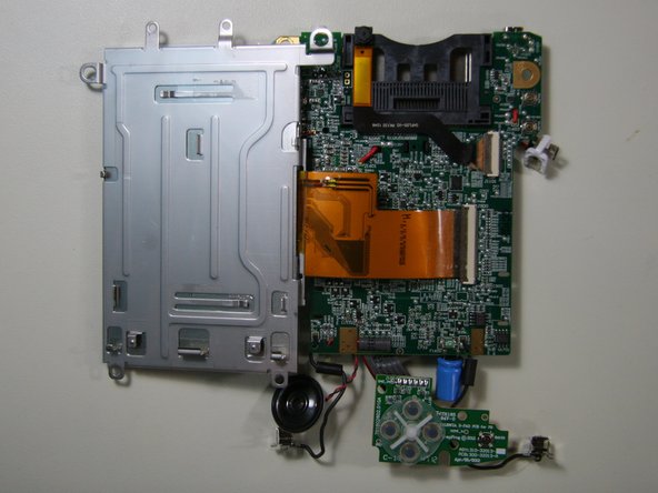
- Holding the front cover with one hand and the sides of the motherboard with the other, lift the motherboard away from the front cover.
- The following may become loose and fall out of position. Reposition them if necessary.
- Front camera lens.
- Buttons.
- If the bracket did not previously fall out after removal of the game cartridge slot screws, remove it now and set it aside for reassembly.
- Front camera bracket location.
- The rubber screen border may separate on its own after removing the front cover from the screen assembly and motherboard. Set it aside if it comes off.
- Pay attention to the original orientation of the rubber screen border to facilitate reassembly.
- Screen assembly tab locations.
- Slide the motherboard in the direction of the game cartridge slot until the motherboard is out from under the metal tabs on the screen assembly.
- Carefully flip the motherboard over by pivoting away from the screen assembly along the long edge with the microphone and speaker, as shown.
- The motherboard and screen assembly are still connected by a ribbon cable that can be damaged if stressed severely.