Nikon Coolpix S8000 LCD Display Replacement
ID: 74915
Description: This guide describes how to replace the LCD...
Steps:
- For safety reasons take off the batterie during disassembling the camera.
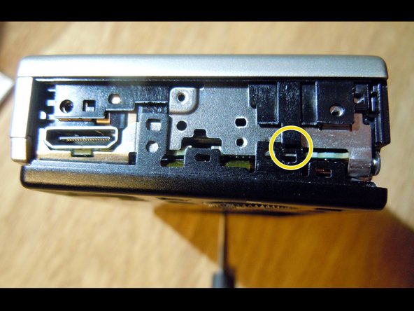
- Remove three phillips screws, 2 short screws (red) and the longer one (yellow)
- The S 8000 is held together by screws which come in several sizes. Make sure to keep your screws organized so that you don´t lose or misplace them!
- On the right side (where the HDMI slot is located) remove two short (red) and one longer screw (yellow).
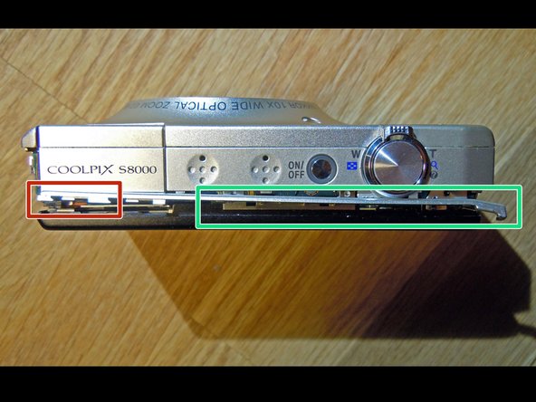
- Now the two covers can be removed.
- Be carefull while pushing the sensitive slim cover (green) downwards.
- Remove two screws and take off the bracket (red).
- The (yellow) screw holds the black rear metal frame and has to be removed.
- Remove the two screws on the left side of the camera, take off the side panel.
- Now you will see three different screws which holds different parts of the camera. All three screws have to be removed.
- The next steps describes the removal of the black metal frame.
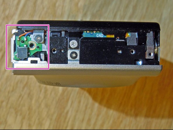
- Be careful, do not touch the open contacts on the left side (pink)! You will be surprised by a "wake-up" electrical shock even 15 minutes after turning off the camera. The flash-condenser still holds enough energy!
- Start on the right side of the camera. There is a small black plastic clip (yellow) which has to be lifted up a little bit. Slowly and carefully begin to separate the rear metal frame from the camera body.
- A critical part is the very slim plastic cover on top (green). The red marker will show you in which direction you have to move this sensitive plastic part.
- Taking off the control panel is not that easy: The panel has two small metal clips at the bottom and one on the top which holds the panel in position. Slightly move the control panel to the top for release.
- Pull the flat cable out of its socket and remove the control panel.
- The LCD display is only laying on the grey insulation foil and has its grounding connection by the yellow marked cupper spring.
- The display has two flat cables connected to the mother board. You have to pull out these cables.
- You´re done!