Kodak DX3500 Digital Camera Teardown
ID: 75114
Description:
Steps:
- Some pretty pictures of the device! On the underside are the first two screws to remove!
- Open the battery compartment and you'll find 3 screws to remove.
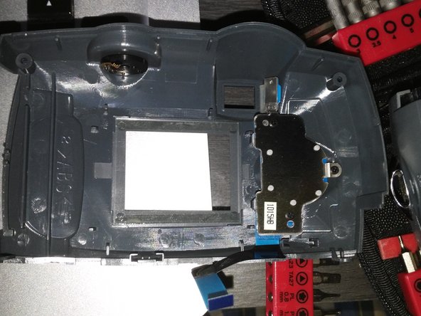
- Pry the bottom off and you'll see the internals! Yay!
- So, I looked at the bottom and nothing more was to be found. Flipped the camera about and found two screws on the outside at the back. Remove those and the rear case pops out.
- Well, here's the mainboard. Time to remove screws. There's lots of them, but first, remove the one holding the display in.
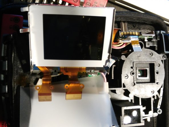
- Flip the display up and pry the two connectors away from the mainboard.
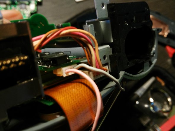
- Then finally pry the power connector away.
- Well, now go haywire and remove every screw you see in the mainboard.
- Then flip the board up and remove the data ribbon cable. (The Orange one). You have to flip up the small brown tab and slide the cable out.
- Remove another power cable
- Flipping open the battery cover reveals one of the many hidden screws in this assembly!
- Time to remove all the screws again!
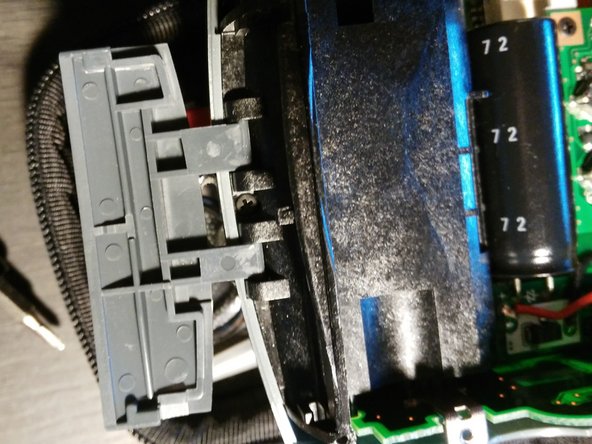
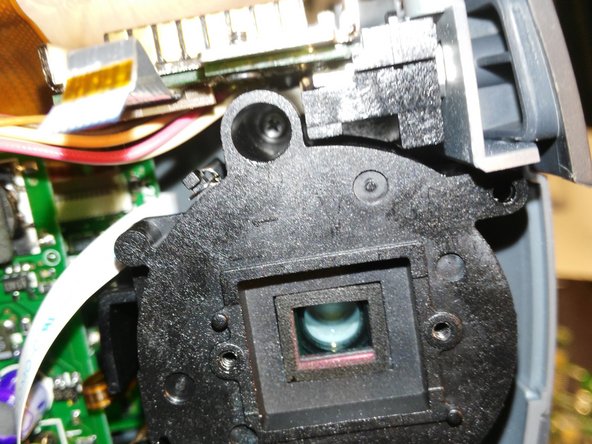
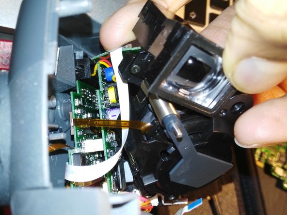
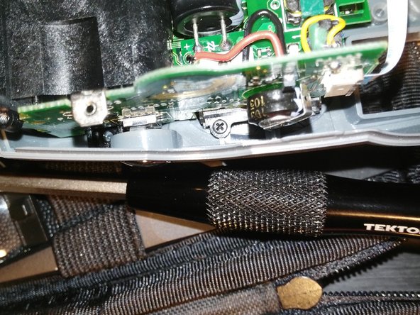
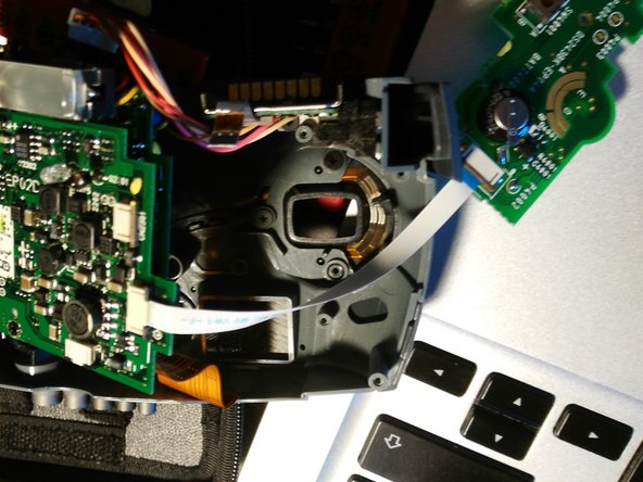
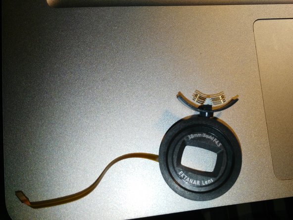
- A couple of hidden ones, but once you get through them, you can pry the lens unit off of the camera, and take care with the ribbon cable here, it seems a bit delicate.
- Easy peasy now, remove another power cable from the bottom.
- Get to the next few screws as well.
- By this point enough screws should've come out and you can pry the front case away and take care with the ribbon again.
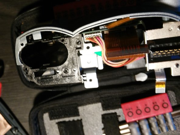
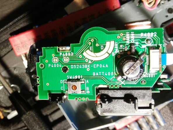
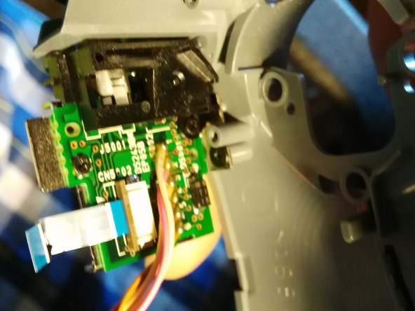
- Flip up to the top and unscrew the board connected to the power button. Should be just one screw.
- Just disconnect the cable and then remove the 3 screws
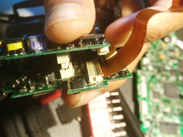
- It will come out in two parts.
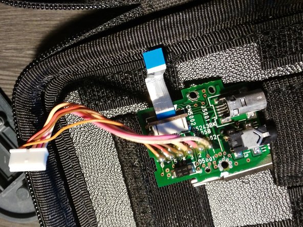
- Flip over to the video out/mini USB port
- Once again unscrew a 3 more screws and voila! We have an I/O board!
- Tired yet? You should be. So fiddly!
- The boards are connected by 1 screw and a male/female connector between the two boards. Be careful here.
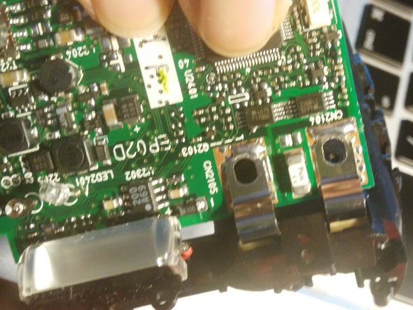
- Unfortunately those hooks aren't just screwed in they're soldered on. You have to very carefully remove them from the battery unit.
- All is done. You can disconnect other sub-units down a bit more, but it's pretty straightforward. If you have a faulty flash you probably need to replace this entire board unit.
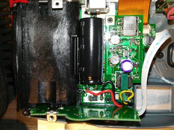
- Note the large capacitor connected to the flash. Be VERY careful around this, it can hold a large amount of charge which could discharge into you, if you touch the ends, or into other electronics it comes in touch with.
- Thanks for reading. This is my very first teardown, and I admit not all the images are great, need to get used to one handed photo taking. Hope this helps someone. I'm guessing most digital camera's of this type will have similar components!