Ersa i-CON 1 soldering station display backlight replacement
ID: 75194
Description: We have about 25 of these soldering stations in...
Steps:
- Pull off the control knob using a nylon spudger.
- Alternatively, a flat head screwdriver can be used, but be cautious of potential scratches on the metal faceplate.
- Flip the station over and remove the four T20 screws.
- Flip the station back onto its base and lift the top cover up and off the station.
- Use pliers or a wrench to unscrew the four plastic nuts holding the display in place.
- Carefully flip the display upwards.
- Loosen the display connector by pushing up the small brown bars on both sides of the connector with a spudger or similar tool.
- Pull the ribbon cable from the connector.
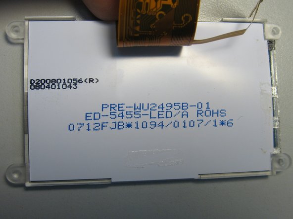
- The display backlight is hidden under white tape on the right side of the display.
- The second photo shows markings on the display.
- Carefully remove the white cover tape using a knife or similar tool.
- Make sure the golden flexible circuit board strip doesn't bend upwards along with the cover tape!
- Use a knife or similar tool to hold down the circuit strip and unstick it from the cover tape.
- If you choose to remove any strip glue residue with alcohol, be careful not to let it seep between various layers inside the display area, as this can cause unsightly spots to develop.
- Use a knife or similar tool to carefully unstick the circuit strip from the plexiglass base.
- The strip is held in place with a thin, transparent, double-sided tape. Be sure to keep the tape on the plexiglass base as you remove the strip. If the tape tears away with the strip, use the tip of the knife to push it back onto the plexiglass.
- Try to bend the strip as little as possible to make it easier to seat back in properly later.
- Fold the circuit strip onto the back cover of the display and weigh it down. This will expose the faulty original LEDs and some resistors.
- Before soldering, place heat-resistant material under the strip to prevent damage to the display's plastic back cover. If the plastic melts, it can cause unsightly spots. In the photo, several sheets of paper are used.
- After analyzing the original backlight connections, it became clear why it fails: the Chinese designers who created the display wanted to save space and money by connecting the LEDs in parallel.
- However, since each LED has a slightly different threshold voltage, one of them draws more current and fails prematurely. The remaining two LEDs then experience even higher currents and burn out soon afterwards.
- To address this issue, I decided to change the connection according to the lower schematic. I shorted the original 22R resistors and put a 220R resistor in series with each new LED.
- There is enough room on the strip to solder in new LEDs (red arrows) along with their 220R resistors (green arrows) on the original solder pads.
- Use resistors in the 0603 package to fit them into the available space.
- Desolder the original 22R resistors and short their pads with a thin wire.
- Verify that all three new LEDs work by connecting a 5V power supply onto the "A" and "K" pads on the strip.
- Stick the circuit strip back onto the plexiglass base.
- Keep in mind that the new components are slightly wider, so make sure the strip doesn't bulge or stick out anywhere. If the strip doesn't fit properly, unstick it and try a slightly different position until it sits flat and securely.
- Secure the strip in place with a new tape cover, such as brown electrical tape.
- Ensure that the tape covers the strip completely and doesn't leave any gaps or exposed areas.
- Reassemble the soldering station carefully and test the display to confirm that it's working properly.
- Here you can see comparison of original (left) and new backlight (center). The new backlight is slightly brighter than the original; you can use larger resistors (270 or 330R instead of 220R) to lower the brightness.
- I also experimented with general-purpose VLMW11R2S2-5K8L-08 omidirectional LEDs. You can see the result on the station on the right - the display is rather dim and there is significant backlight bleed on its right edge, where the LEDs are located. Thus I recommend to use only directional, right-angle LEDs like LTW-108DCG-HS10.
- Since new LEDs need lower current to achieve similar light output, they should outlast the soldering station. This "trick" is generally applicable; high-brightness LEDs always generate more light at 2 mA than ordinary LEDs at 20 mA. At the same time, they consume less power, generate less heat and last much longer.