Handson Fan Heater 2000 Watt Electro Motor (yj58-12a1) Replacement
ID: 78992
Description: By replacing the electro motor, which powers th...
Steps:
- Unplug the power cord.
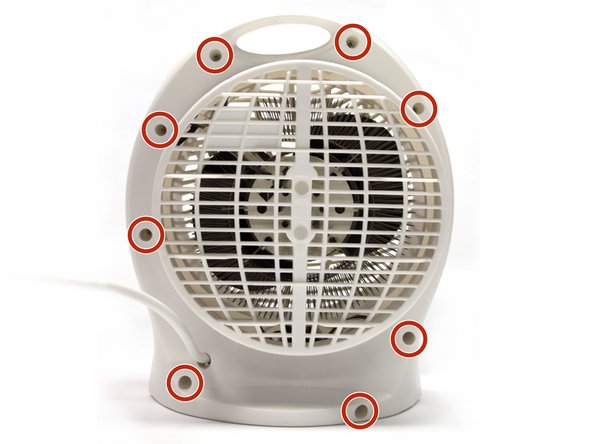
- Flip the device over so the bottom is revealed.
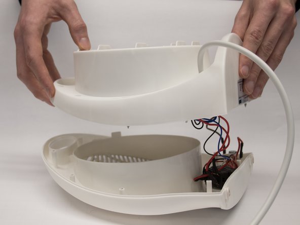
- Unscrew the nine screws (3x12mm) using a Phillips (1x75) screwdriver to open up the housing of the fan heater.
- Don't worry if the white rubber support feet fall out when taking the two housing halves apart.
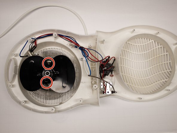
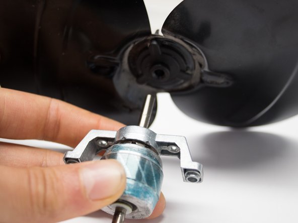
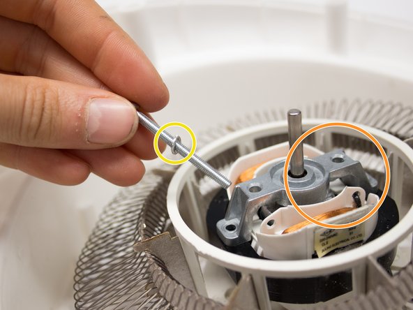
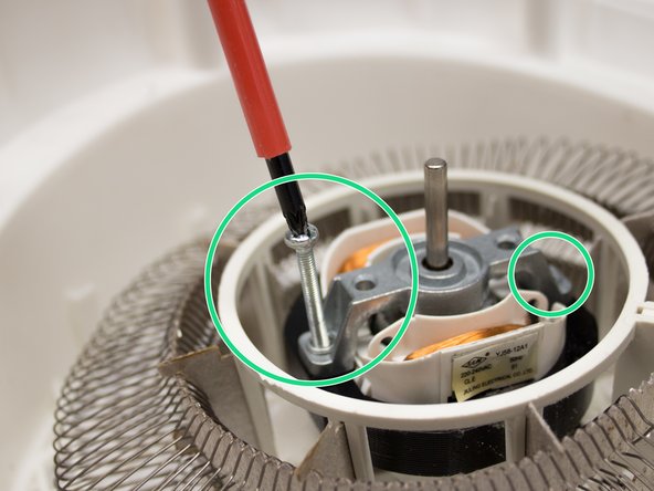
- Unscrew the two screws (3x40mm) on either side of the blades using a Phillips (1x75) screwdriver.
- Be careful not to loose the metal rings surrounding the screw thread.
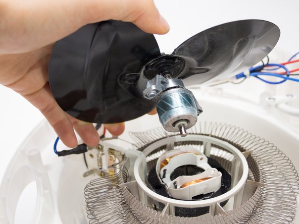
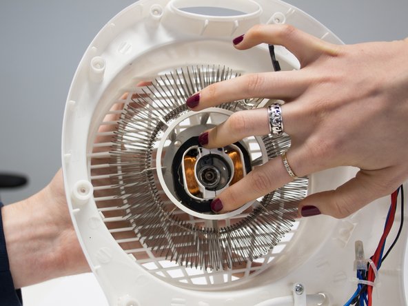
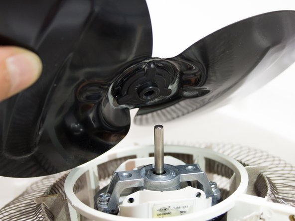
- Take off the blades by gently pulling up the middle.
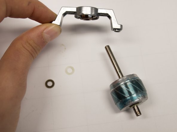
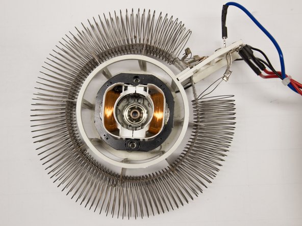
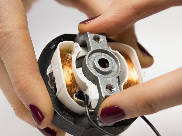
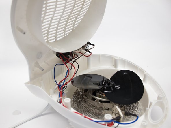
- The two engine parts are now revealed: a slightly blue part attached to the blades and another part that is attached to the housing of the fan.
- Remove the blades from the axle which is part of the electromotor.
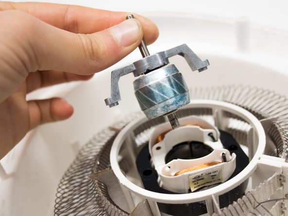
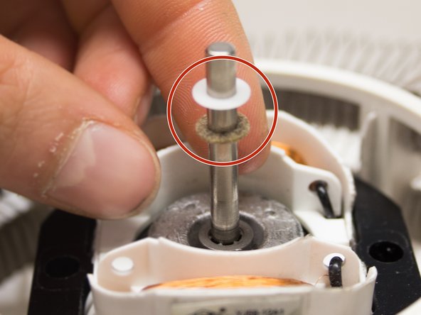
- When removing the axel bridge of the upper part of the motor, make sure you store both the felt and plastic ring carefully. These will be needed for reassembly.
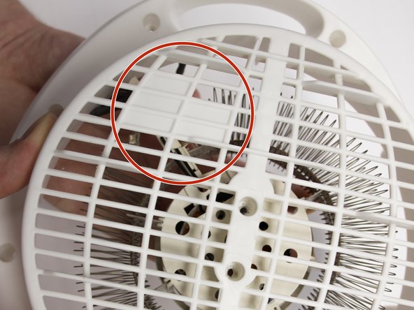
- Flip the housing of the fan heater over to reveal its bottom.
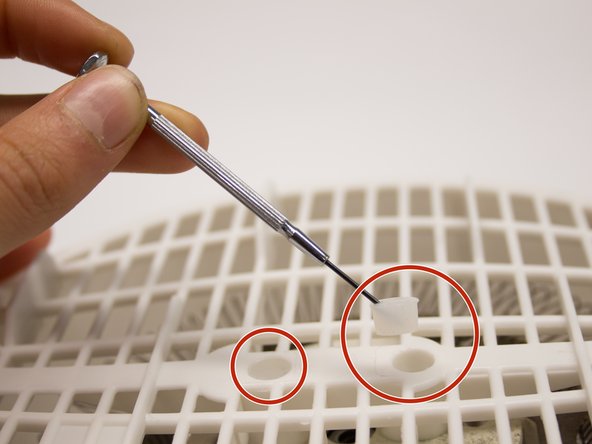
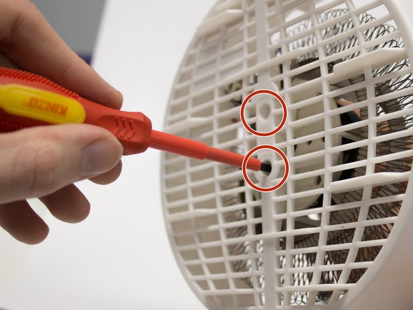
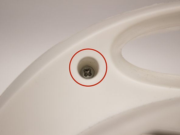
- Use a metal spudger to remove the two rubber sealing caps and reveal the two screws.
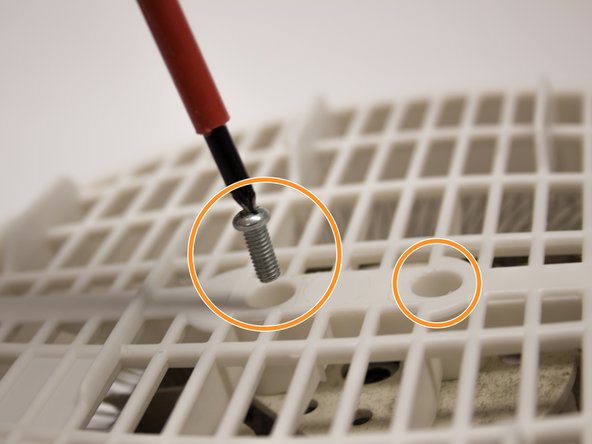
- Unscrew the two screws (3x12mm) using a Phillips screwdriver (1x75) to separate the electro motor housing from the fan housing.
- Be careful - the electromotor housing will drop when the screws are removed!
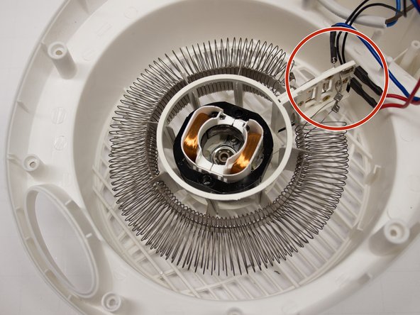
- Turn the fan housing back around to reveal its inside.
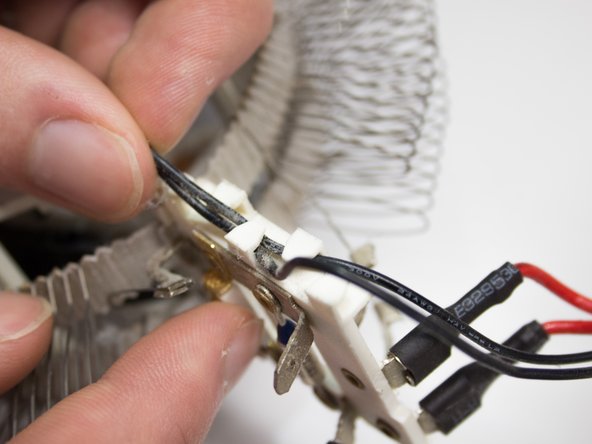
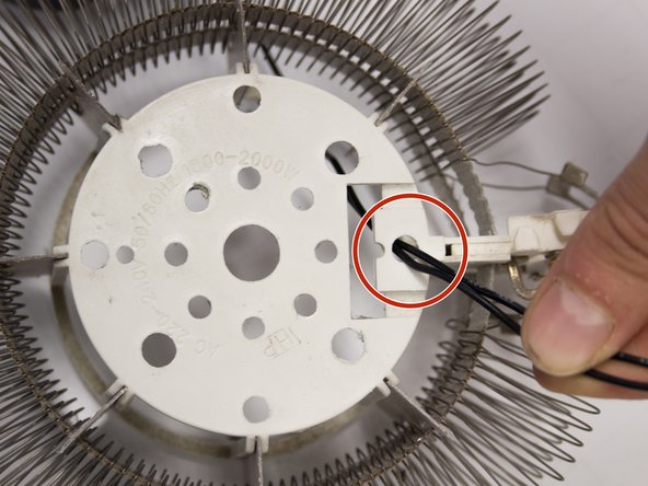
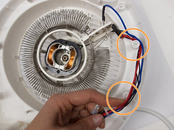
- Remove the black wire from its plastic support piece.
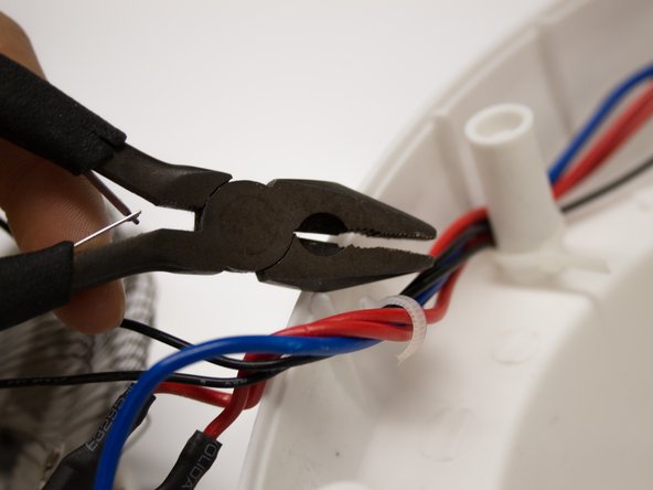
- Remove the tie wraps around the wires to allow some space to reach the electro motor.
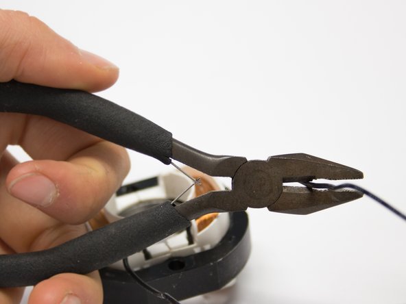
- Use pliers to snip the black wires.
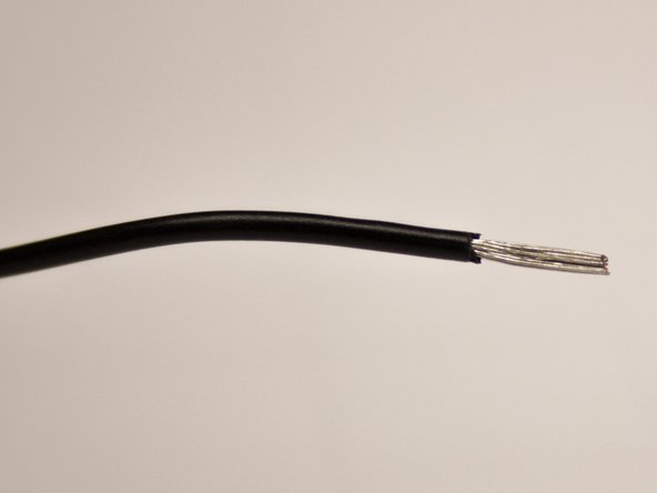
- Use a wire stripper to remove the plastic cable housing and reveal the electrical threads.
- Thread the wire connected to the new electro motor through the right hole in the pastic motor housing.
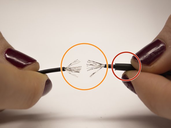
- Lay the heat shrink upon one of the wire halves.
- Feather apart the electric wire on both halves.
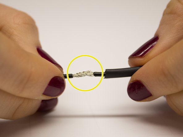
- Weave together the wiring of the two halves so they create one wire.
- Shove the heat shrink over the woven electric wire.
- Use a heater such as a blowdryer or lighter to warm up the heat shrink and seal the wire halves.
- Be careful not to burn your fingers or the heat shrink.
- Repeat this step twice as two wires need to be connected.
- Place the metal axle bridge on the new electro motor.
- Place the heating element back in the housing, making sure the plastic part where the cables are connected is placed on the housing without holes.
- Make sure the wires are stored in the right place.
- Make sure the two sides of the metal coil on the heating element do not touch to avoid short circuit.
- Flip over the housing of the fan to reveal the bottom of the housing.
- Place the two screws into the holes on the rear side of the housing.
- Place the heating element over the screws.
- Make sure the bottom of the engine with the axle bridge is placed in its position in the middle of the heating element. If possible ask someone to help, an extra pair of hands will come in handy.
- Fasten the screws to secure the heating element in place.
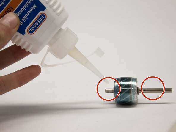
- Apply lubricant to the axle, we used mineral oil from “Pressol”.
- Place the axle in the middle of the engine
- Place the felt ring on the axle and the plastic ring on top of it.
- Place the axle bridge on the axle.
- Place the small metal ring over the longest screw.
- Secure the parts in place with the two screws on either side using a Phillips screwdriver (1x75).
- Place the blades on the axle while making sure to press them down.
- About 1 cm of axle should be visible between the blades and the axle bridge.
- Finally put the two housing halves back together and secure the nine screws.