ASUS U46E-RAL7 Motherboard Replacement
ID: 79051
Description: In this guide, the user will be able to follow...
Steps:
- Remove two (2) 9mm x 4mm screws from the back panel with the size 0 Phillips head screwdriver.
- Remove two (2) 7mm x 4mm screws from the back panel with the size 0 Phillips head screwdriver.
- Remove six (6) 7mm x 4mm screws with the size 0 Phillips head screwdriver.
- Remove three (3) 3mm x 3mm screws with the size 0 Phillips head screwdriver.
- Remove one (1) 4mm x 4mm screws with the size 0 Phillips head screwdriver.
- Remove the rubber caps (4) with the tweezers. If the rubber caps are not removed easily, pull gently. The caps are glued down.
- Remove four (4) 7mm x 4mm screws with the size 0 Phillips head screwdriver.
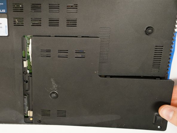
- Remove the L shaped panel with the plastic opening tool by inserting it into the indent along the USB port side of the laptop.
- Push down gently on the plastic opening tool until part of the panel pops up.
- Use your fingers to pop the panel off.
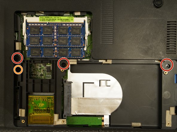
- Remove three (3) 5mm x 4mm screws with the size 0 Phillips head screwdriver.
- Remove one (1) 4mm x 4mm (closest to the battery) screw with the size 0 Phillips head screwdriver.
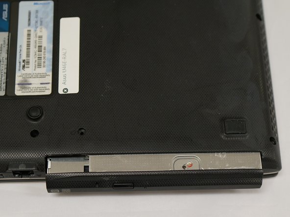
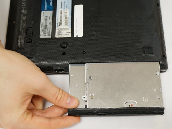
- Remove the CD ROM drive by inserting the plastic opening tool between the drive and the laptop's side.
- Push down gently to eject the drive.
- Pull the drive straight out to remove the part from the laptop.
- Remove three (3) 3mm x 3mm screws with the size 0 Phillips head screwdriver.
- Flip the device so that the laptop will open away from you to remove the hinge cover behind the screen.
- Place index fingers underneath the hinge cover and gently pull up.
- The cover will pop off easily with a click.
- Remove five (5) 5mm x 4mm screws from the hinge compartments of the device with the size 0 phillips head screwdriver.
- Open the screen.
- Carefully lift the keyboard panel. The keyboard will be attached to the motherboard by two ribbons.
- To disconnect the ribbons, use your fingernails to push down gently on the protruding plastic at the base of the connector. There is a soft click and ribbon releases. Repeat for the other ribbon.
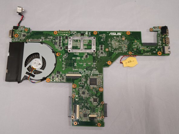
- Remove the keyboard from the computer to reveal the motherboard.
- Remove four (4) 7mm x 4mm screws with size 0 phillips head screwdriver.
- Remove thirteen (13) 5mm x 4mm screws with size 0 phillips head screwdriver.
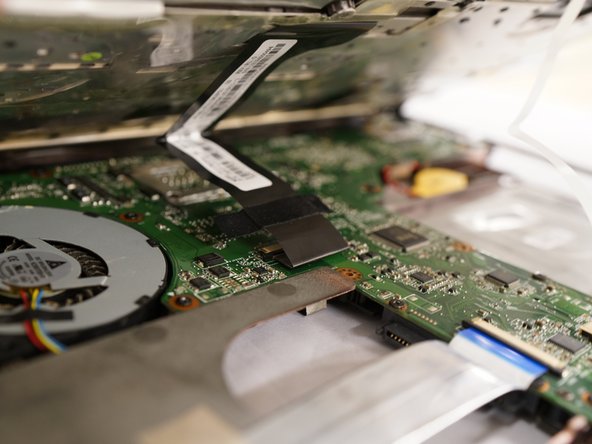
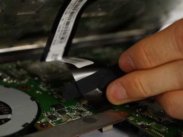
- Disconnect ribbon from bottom left corner of motherboard.
- Use your fingernails to push down gently on the protruding plastic at the base of the connector. There is a soft click and the ribbon releases.
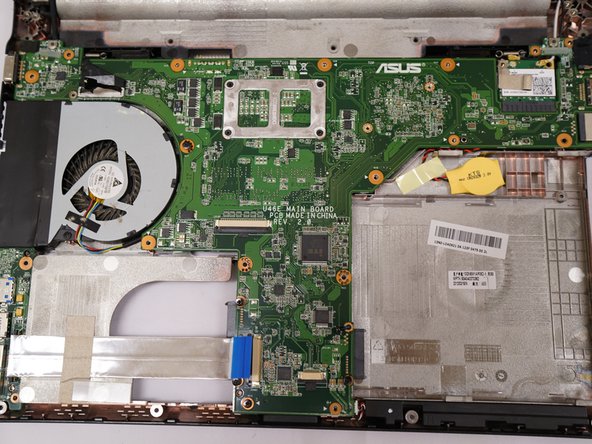
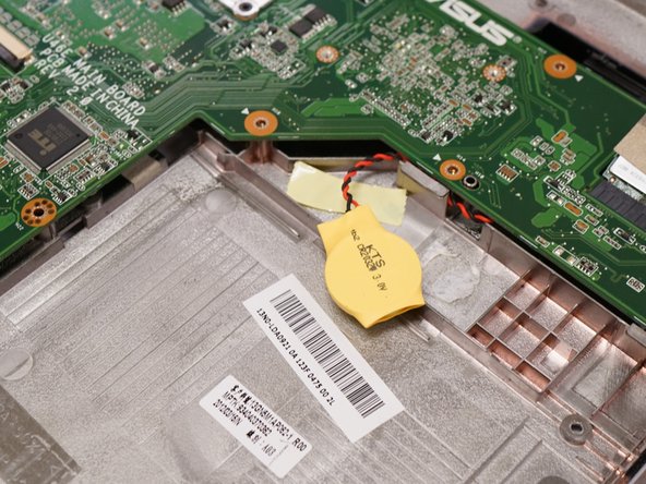
- Disconnect one (1) white/red/black connector wire by prying it up with the spudger.
- Disconnect one (1) red/black connector wires by prying them out with the nylon spudger.
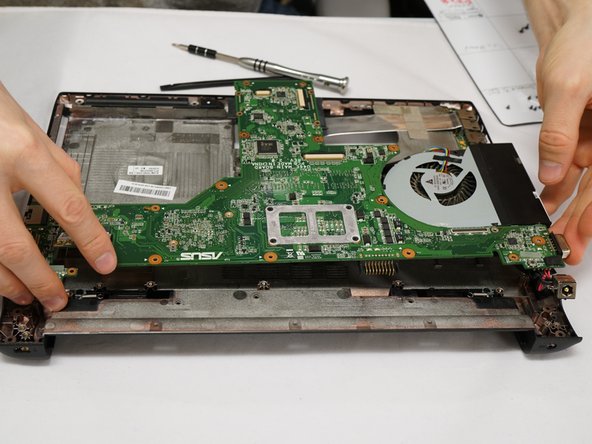
- Insert index fingers underneath the motherboard in the top corners of the motherboard. Slowly move your fingers toward the center of the board while lifting up gently. The motherboard will lift easily from the device casing.