VTech InnoTab Max Motherboard Replacement
ID: 79862
Description: This guide will show how to replace the...
Steps:
- Remove all screw caps from the back panel using a metal spudger.
- Next remove all of the now uncovered screws.
- If there is a cartridge in the device make sure to remove it.
- Now that all of the screws have been removed, pry the back cover off using a plastic opening tool.
- Here you can see the back cover has been fully removed and you can now access the front cover.
- To remove the front cover, remove the springs holding the pictured brackets in place, then pull it away.
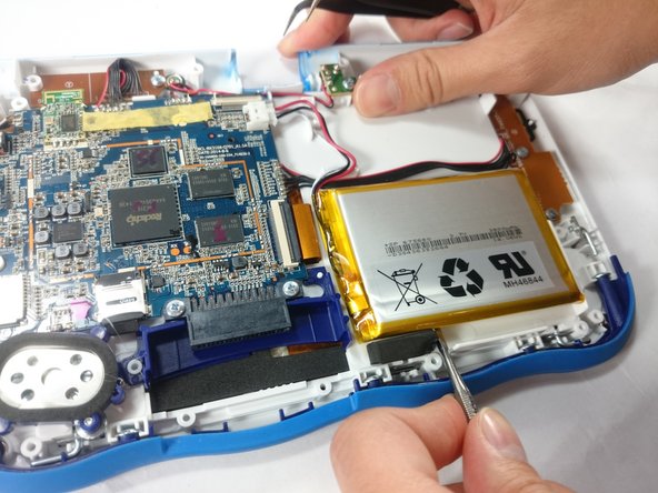
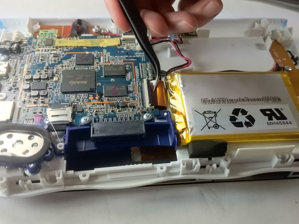
- Once the back cover is removed the battery will be located in the bottom right as you can see in the image to the right.
- Remove the tape holding down the wires, and carefully pry the battery off of the base of the device.
- Pry carefully to avoid damaging the battery. The battery may start to bend slightly, this is normal and not a cause for concern.
- It is best to use a plastic card or nylon spudger to remove the battery. Metal tools can puncture a battery, potentially causing a fire.
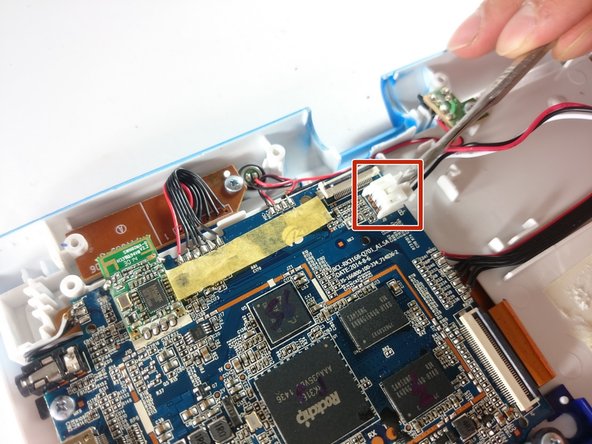
- Now that the battery is free to be moved, unplug the wire connecting the battery to the motherboard.
- The battery is now fully disconnected.
- The camera is not held down by anything, so simply remove it from it's spot to prepare for unplugging it.
- Carefully remove the wire connecting the camera to the motherboard, using a tool to grip it if needed.
- Be careful to only pull from the end of the connector (closest to the motherboard), as the strip is easy to tear.
- The camera is now removed completely removed from the device.
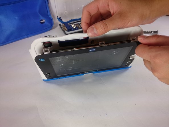
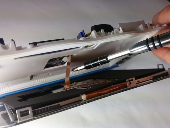
- In order to unlock the screen you need to remove the 4 pins that can be seen in the picture.
- To remove simply just turn and pull them out. Use a metal or nylon spudger if they are too small to grip.
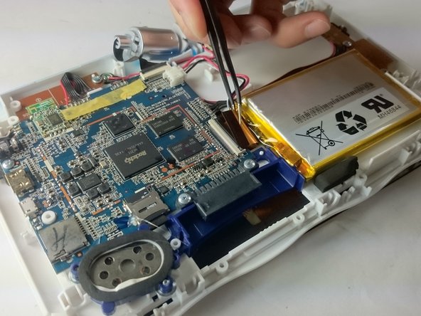
- Once the pins are removed the screen should be loose from the frame and only connected by the brown film pictured.
- In order to completely remove the screen you need to unclip the film from the motherboard by simply using a pair of tweezers and gently pulling.
- Be careful not to tear the film when pulling.
- Once unclipped from the motherboard the screen should be entirely free from the device
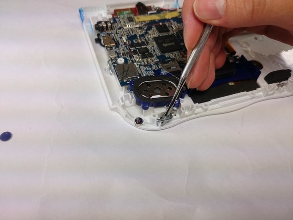
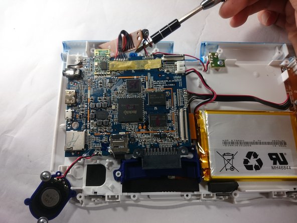
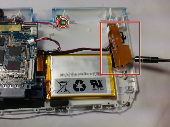
- Remove the circled screws that are holding down the motherboard and components.
- Every component that will need to be unscrewed will have wires running to it from the motherboard. These wires will not be disconnected.
- With all of the screws out, lift up the speaker, the two visible bronze plates, and the small green chip at the top.
- Do not try to disconnect any of the wires running to these devices, as you will not be able to reconnect them.
- All of these components can be located by following wires leaving the motherboard.
- With all of these components out of their place, lift up the motherboard to reveal one more bronze plate.
- Remove the screws holding down this plate, and remove it with the rest of the motherboard.
- All components should be free from the device, and you can now completely remove the motherboard.