Canon PowerShot G1 X View Finder Zoom Replacement
ID: 87505
Description: If the viewfinder wheel on your Canon PowerShot...
Steps:
- To begin removing the back camera casing, unscrew the Phillips screw underneath the panel covering the USB connections on the side of the camera. Use a Phillips Head 00 screwdriver for this screw.
- Remove the screw located directly beneath the USB cover located in the second photo. Use a Phillips Head 00 screwdriver for this screw.
- After removing the first screw flip to the bottom side of the camera and unscrew the two screws located toward the back side of the casing. The screw on the front side can be left in. Use a Phillips Head 00 screwdriver for both of these screws.
- Now flip to the opposite side of the USB panel screw and unscrew the two screws holding the small speaker cover portion of the camera. Use a Phillips Head 00 screwdriver for both of these screws.
- The last screw is located towards the top side of the back of the camera next to the view finder. Unscrew by using a Phillips Head 00 screwdriver.
- Remove the side panel covering the speaker by gently pulling it away from the camera. You can also use spudgers to create a lever to help remove the panel.
- Remove the back casing by gently pulling. You could also use spudger to create a lever to help pry it off.
- Locate the view finder zoom on the back of the camera.
- Remove the screw using a Phillips #000 screwdriver.
- Be careful, the viewfinder zoom wheel can fall if the camera is oriented vertically.
- To remove the viewfinder wheel, pull it to the left and away from the camera.
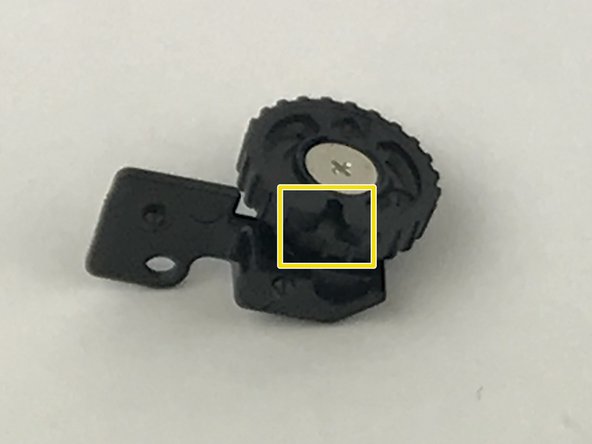
- Locate the viewfinder zoom pin seen in the first image.
- Orient the viewfinder zoom pin to the same orientation as in the first image.
- When reinstalling the viewfinder wheel, orient the notch in the viewfinder zoom wheel seen in the second image with the pin seen in the first image.
- This will allow for the full range of motion of the viewfinder zoom wheel. Improper orientation will lead to a lower range of motion which can cause damage to the viewfinder.