Motorola Moto G4 Plus LCD Screen and Digitizer Assembly Replacement
ID: 87638
Description: This guide will walk you through the process of...
Steps:
- Insert a fingernail or a spudger into the notch on bottom edge of the phone near the charging port.
- Pry the back cover away from the body of the phone.
- Continue to gently lift the back cover until all plastic clips have been released.
- Remove the back cover.
- To reinstall the back cover, align the cover over the body and gently press all around the edges until you feel the clips snap into place.
- Slide out and remove the SIM card.
- Remove the nineteen 3.1 mm T3 screws securing the midframe.
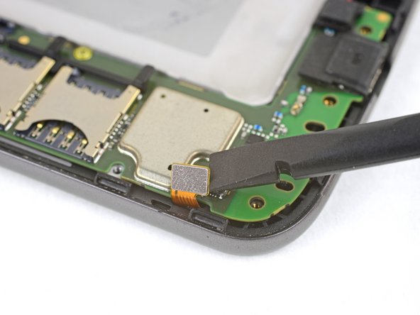
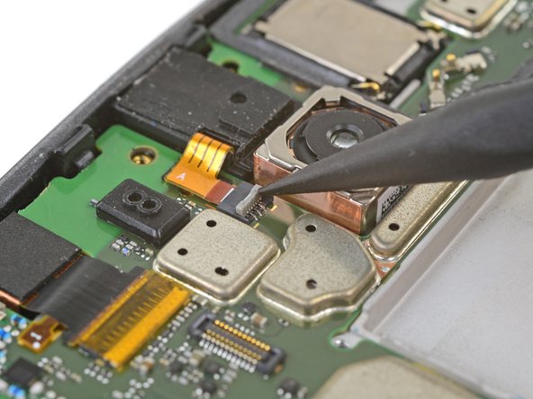
- Use the point of a spudger to pry up the rubber cover over the camera flash connector.
- Remove the rubber cover.
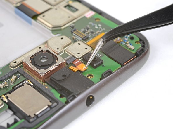
- Use the point of a spudger to pry up and disconnect the camera flash connector.
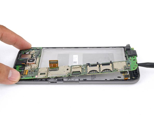
- Loosen the midframe along the edges and lift it away from the body.
- Remove the midframe.
- Be very careful not to puncture the battery with any sharp tools. A damaged lithium-ion battery can catch fire and/or explode.
- Peel up and remove the tape securing the battery wires.
- Peel up and remove the black tape that bridges the battery and the phone.
- While neither tape pieces are necessary for the operation of the phone, save them if they are in good condition for the reinstallation process.
- Slip the point of a spudger underneath the red and black battery wires and gently pry straight up.
- Do not pull the plug out, or you will tear the board socket out. Be careful where you pry. Do not pry against the board socket.
- During reassembly, align the connector in its socket, then press straight down to reconnect it.
- Use tweezers or your fingers to de-route the battery wires from the plastic brackets.
- Peel the black pull tab from battery and pull slowly but firmly to separate the battery from the frame.
- A few drops of high concentration (90% or higher) isopropyl alcohol along each side may help soften the adhesive.
- If the pull tab breaks, use a spudger to gently pry around the edges of the battery until it comes loose.
- Don't deform or puncture the battery—it can catch fire and/or explode if damaged.
- Never reinstall a damaged or deformed battery. Replace the battery.
- Remove the battery.
- To install a battery, orient the new battery such that the wires exit near the bottom of the phone, and the battery connector is on the motherboard side.
- Clean off any adhesive residue which may prevent the battery from sitting flush against the frame. Use a few strips of adhesive included in the battery kit or some double-sided tape to secure the battery to the frame.
- Peel away the yellow tape over the T3 screw next to the SIM card slot.
- Peel away the copper tape covering the display connector.
- The copper tape provides protection to the display connector. Try to keep it in one piece for reinstallation.
- Slide the point of a spudger underneath the vibration motor's wires.
- Gently pry up to free the vibration motor from its recess.
- During reinstallation, align the vibration motor with its recess and press down.
- Use a spudger to pry up and disconnect the home button cable connector from the motherboard.
- Use a spudger to pry up and disconnect the display connector from the motherboard.
- Use tweezers to remove the yellow tape protecting the headphone jack's connector.
- Use the point of a spudger to carefully flip up the headphone jack's grey ZIF connector lock.
- Use tweezers or the point of a spudger to carefully walk the ribbon out of the ZIF connector.
- For reinstallation, align and reinsert the cable into the ZIF connector so that the white line on the cable barely shows. Flip the ZIF connector lock back down.
- Remove the two 2.4 mm T3 screws next to the SIM card slot.
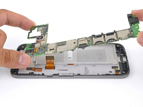
- Insert the point of a spudger into a groove at the bottom of the motherboard.
- Gently pry up to loosen the motherboard from the frame and from the edge clips.
- Use a spudger to move any flex cables out of the way, as well as making sure that any modules attached to the motherboard (such as the front-facing camera) are loose from the frame.
- If you feel any resistance, stop. Make sure there are no components still holding the frame to the motherboard.
- Lift the motherboard up from the frame and remove it.
- To remove the headphone jack to transfer it to the new frame, insert the point of a spudger into the headphone port, and twist downwards to pop the jack out of the frame.
- Remove the headphone jack.
- To install the headphone jack onto the new frame, align it over where it should be and press downwards.
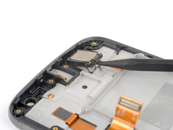
- To remove the earpiece speaker to transfer it onto the new frame, insert the point of a spudger at the bottom of the speaker.
- Pry upwards to separate the earpiece speaker from the frame.
- To install the earpiece speaker onto the new frame, check and replace the adhesive if necessary. Align the speaker such that the two spring contacts are oriented as shown in the picture.
- Only the LCD screen and digitizer assembly (with frame) remains.
- Compare your new replacement part to the original part. You may need to transfer remaining components or remove adhesive backings from the new part before installing.