Roku 4 Ethernet Port Replacement
ID: 87656
Description:
Steps:
- Place the Roku 4 face-down on a table. The rubber sticker should be facing you.
- Starting at one corner of the device, pull the rubber sticker back toward the opposite corner of the device carefully to reveal the underlying screws.
- Completely remove the rubber sticker to reveal the underlying screws on the device.
- Place the rubber sticker facing up on the table to preserve its adhesiveness. It will be needed to reassemble the device.
- Turn the Phillips PH1 screwdriver counterclockwise to unscrew all 4 of the 12.0 mm screws.
- Store the screws in a safe place, such as on a magnetic project mat, so they do not get lost before reassembly.
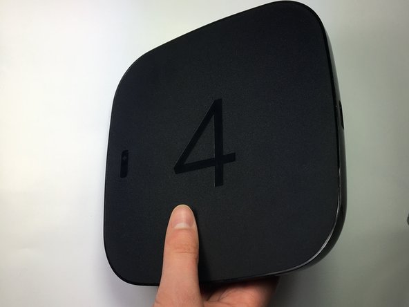
- Turn the device over so you can see the "4" on the top cover.
- Wedge a plastic opening tool into the seam between the top cover and bottom casing of the device and create a gap.
- Prying open the device is quite difficult and requires a large amount of force. Use caution to avoid breaking the device or hurting yourself.
- After you have created a gap large enough to fit your fingers between, gently lift up the top cover to open the device and reveal the motherboard.
- The motherboard should still be attached to the underside of the top cover by a red wire, a blue wire, and a black wire.
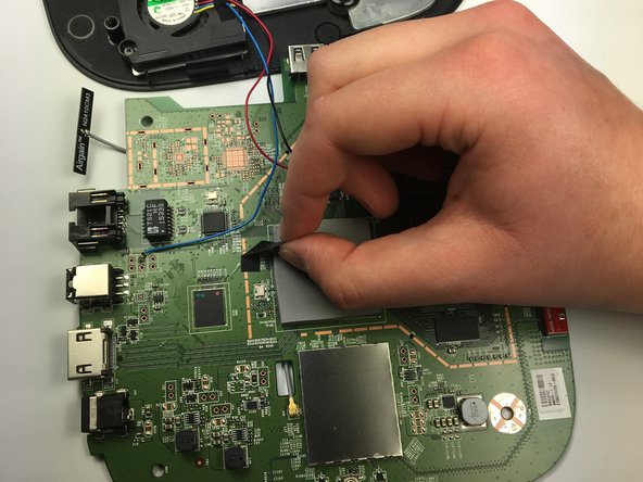
- To begin removing the motherboard from the plastic casing, pinch the black plastic clip and gently pull upward.
- Once you feel the motherboard begin to loosen from the plastic casing, pull it upward to remove it completely.
- The motherboard should still be attached to the underside of the top cover by a red wire, a blue wire, and a black wire.
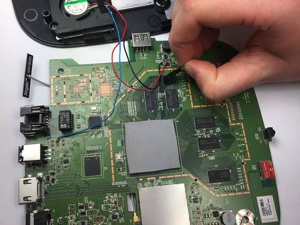
- Peel back the black adhesive strip that attaches the blue wire to the motherboard.
- Repeat this step for the strip that attaches the black and red wires to the motherboard.
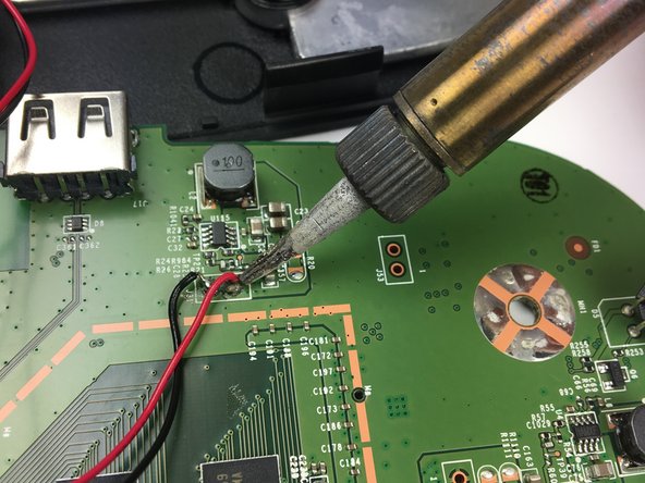
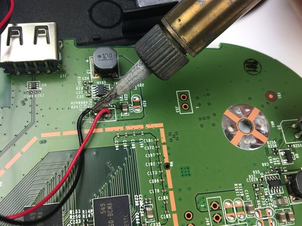
- Using a soldering iron, desolder the blue, red, and black wires from the motherboard.
- Consult iFixit's Soldering Skills guide to safely use the soldering iron.
- The motherboard should now be completely disconnected from the top cover of the device.
- Lay the motherboard facedown on the table so you can see the large black ethernet port with several gold connections below it.
- Use a soldering iron to desolder each of the ethernet port's connections to the motherboard.
- Consult iFixit's Soldering Skills guide to learn how to safely use the soldering iron.
- Using your thumb and pointer finger, carefully pinch the Ethernet port and pull it to the right, away from the motherboard, to remove it.