Alcatel Go Play (7048W) Teardown
ID: 87728
Description:
Steps:
- The Alcatel Go Play 7048W running Android 5.0.2. It advertises water resistance, and expandable memory! The processor is a Snapdragon 410 with 4 cores running at 1.2GHz. The display is 5 inches with a resolution of 720 x 1280. 8 GB internal storage, and 1 GB of RAM.
- Some other features are 802.11b/g/n wifi and bluetooth 4.1. Not a bad little phone for $200.
- This device (well two of them) came into my little repair shop from a local phone dealer. Apparently the customers had shoved the SIM cards into the phones without the SIM card tray, then pried them out with tweezers. Now they won't read SIM cards. It all happened before they where even paid for, still in the store. Oh fun!
- On the left, we have a door that exposes the Micro SIM card slot and tray, as well as the Micro SD card slot and tray. The right has power, volume down and up. The bottom sports a Micro USB port, with a door. And the top has a 3.5mm headphone jack (may it rest in peace) with a door.
- All of these doors are for the water proofing, like many other phones. Reminds me of the Galaxy S5.
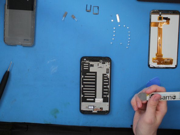
- Taking a iSesmo to the back cover snaps off a few holding snaps around the phone. I do like that sound...
- Taking the back off exposes very little. We find the ability to take off the water proofing doors and two little screws. definitely feeling like an S5 now.
- The screws at the bottom on either side of the charging port are filled in with a hard coating, assuming for water proofing. I had to scrap away at them to access them. I don't think water proofing post repair is going to be a thing.
- Looks like we'll have to go in from the front! That means some heat to melt the adhesive around the screen. Having flashbacks to the Galaxy S5!
- I'm using a hot plate set pretty low. Alternatively you can use a hot air gun, of iFixits iOpener, or even a hair dryer.
- Waiting for the hot plate...
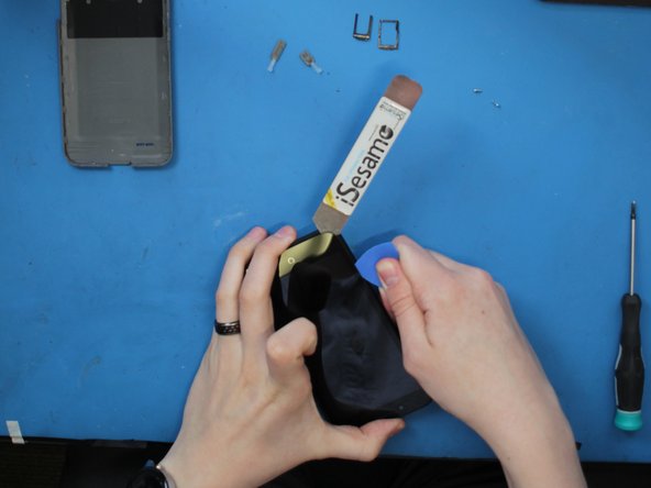
- Inserting the iSemamo gets a little gap started, then I can get my pick in there and slide it down and around the entire screen.
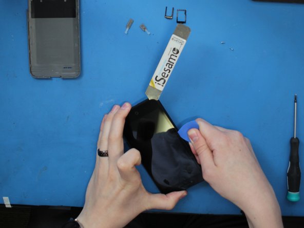
- Remember, if it's hard to separate the adhesive, apply more heat. You do can each side individually. No need to heat the middle, there is no adhesive there.
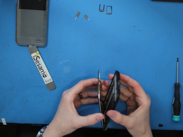
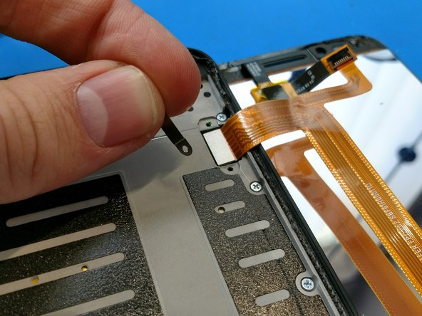
- Prying slowly and taking care not to rip the flex cable, which is attached to the upper right of device, we can take the screen off.
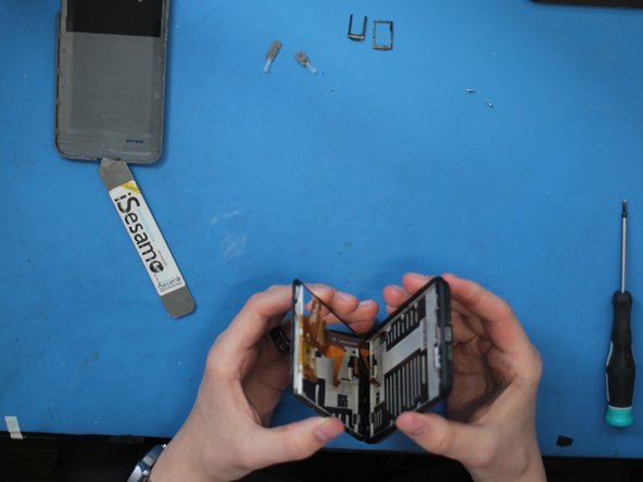
- The screen came off easy and the LCD is fine! My flash back to the S5 has ended, for now.
- Looks like one flex connects the screen assembly to the board.
- Two screws hold down a retention plate that keep the connector in place.
- Screen is off! Also, with closer inspection of the screen assembly, the glass and LCD are NOT separate. my attempts to separate them, even with a hot plate created a crack in the LCD. If you're looking for replacement parts, best to get it as one.
- Charging port looks pretty easy to detach.
- Before we go any further, there are 15 total screws keeping the mid frame in place to the back housing.
- They are all the same, so no worries getting them mixed up!
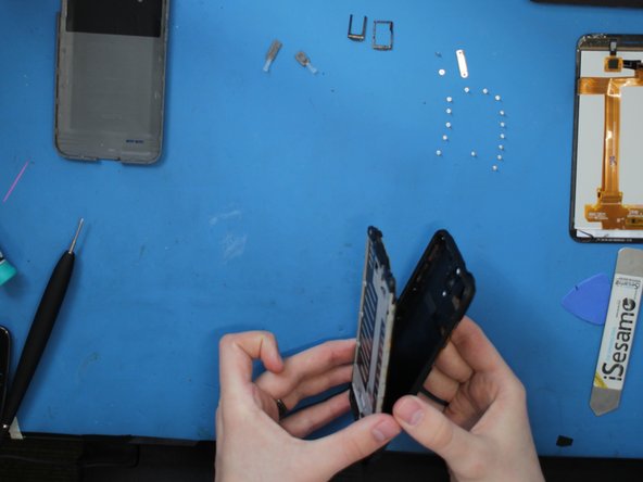
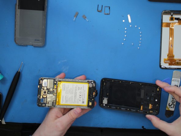
- Using my iSesamo pry tools, I easily took the mid frame assembly out of the back housing.
- Be careful, the charging port comes out at a bit of an angle.
- If I could've, I would've unplugged the battery by now.
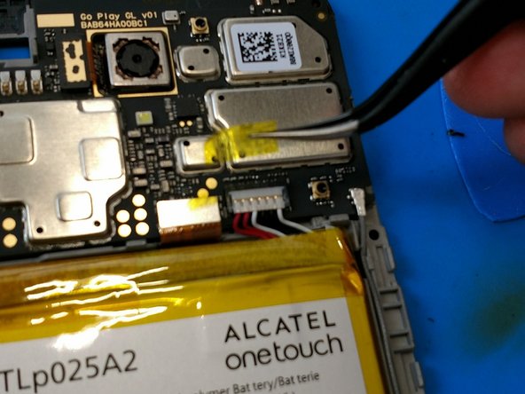
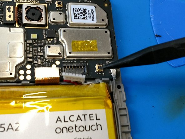
- There is a little bit of Kapton tape over the connector. Then use a plastic pry tool to unhook the battery.
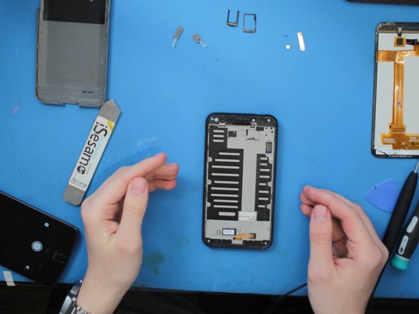
- Sorry for the different colored images, I switch to my phone camera for some closer images.
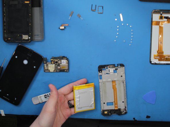
- The battery is a 2500mAH 9.5WH
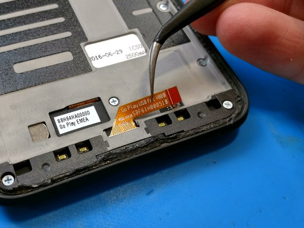
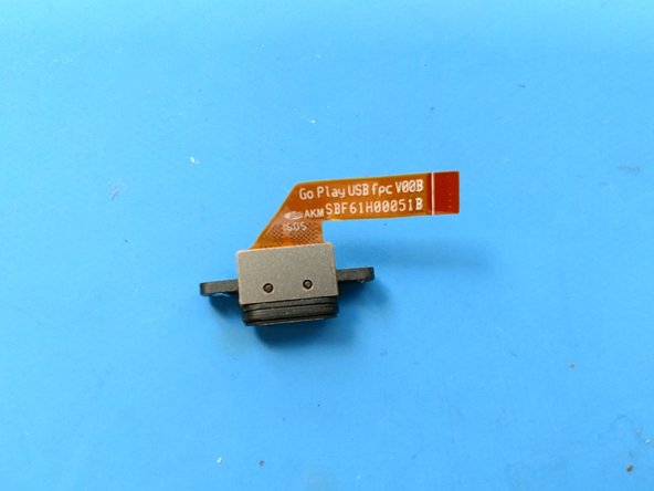
- At this point as well, I can take out the charging port.
- It reads Go Play USB fpc V00B AKM SBF61H00051B
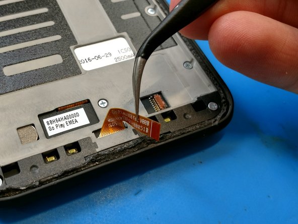
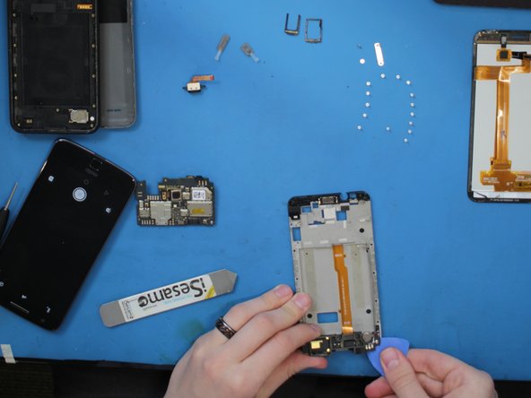
- A quick discount of the daughter board flex and antenna cable releases the board from the mid frame.
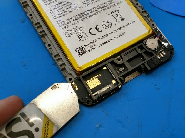
- A wee bit of heat to melt the adhesive, and the daughter board is almost out, looks like we need to take the battery out first.
- A simple prying to the battery with a plastic pick gets it right out. Remember to use plastic, we don't need a Note 7 here.
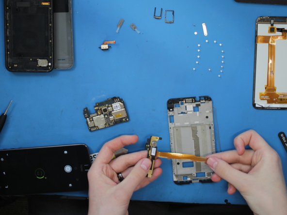
- Some careful lifting of the board and the flex cable gets the board off the mid frame.
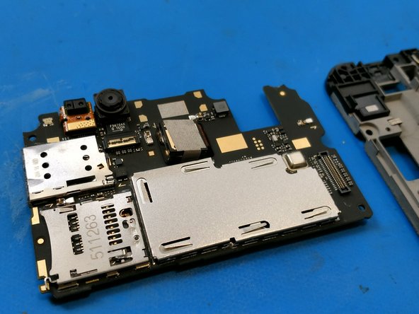
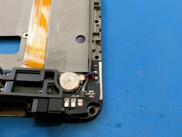
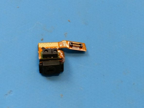
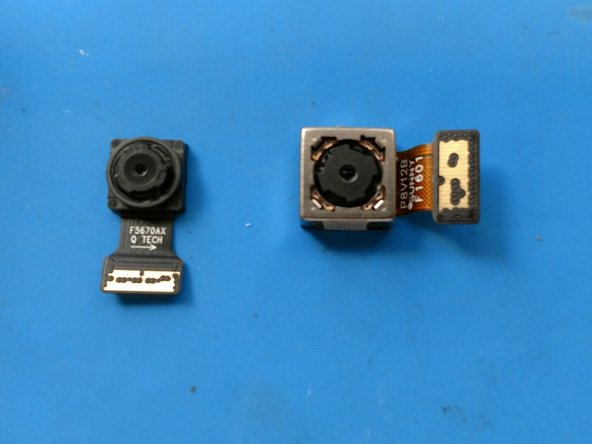
- We have the board out, time to take the proximity sensor, front facing 5MP camera, and rear facing 8MP camera out. All are simple modular parts.
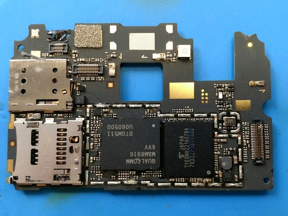
- I went ahead and took off all of the shielding of the board, front and back.
- It also looks like the SIM card port reader is on the board. I have a feeling there is little hope for this as a repair.
- Looks like there is little hope for this. For those of you who may not know, that little part there to the left is the reader, it came right off, and has some of the solder pads attached, they are those pinkish copper looking things on the edges and in the middle.
- Since it pulled the pads off in the original damage, and there are no schematics, I'm not going to even try and run jumpers or rebuilding the pads.