ASUS TV500BG Bluetooth Controller Disassembly
ID: 87819
Description: This is the bluetooth controller that's...
Steps:
- Find the battery compartment on the bottom of the controller.
- Depress the button on the battery compartment. Pull the compartment away from the controller and then slide it out.
- Remove seven 7mm T7 screws on the bottom of the controller.
- Holding the controller upside-down, carefully pull the case apart starting from the back of the controller.
- You'll have to push the battery contact springs through the case as you pull the front of the controller apart.
- Now you can start disassembling the inside! First take the two weights out of their slots at the bottom of the controller (I know, kind of underwhelming, but you gotta start somewhere).
- Remove three 7mm T7 screws that fasten the logic board to the top half of the controller.
- Pull the logic board straight out from the top half of the case.
- To protect sensitive electronic components, always stay grounded when handling circuit boards. It's best to ground yourself with an Anti-Static Wrist Strap.
- Keep the logic board and the controller case parallel to the table so the buttons don't fall out when you take the board off.
- First we'll tackle the top half of the controller case. If you enjoyed pulling the weights out, get excited. This is pretty much the same.
- There are membrane switches under the plastic buttons. First lift out the membrane switches, then the buttons.
- If you're careful you can just flip the controller case over and the buttons will fall out.
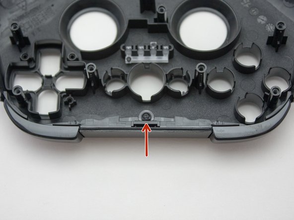
- You cannot remove the bumper buttons without breaking the plastic hinge that holds them (shown in the last photo). If you need to replace these buttons I suggest carefully cutting off the top of the hinge to remove the old buttons. Then you can use a dab of hot glue or something similar to hold the new ones on.
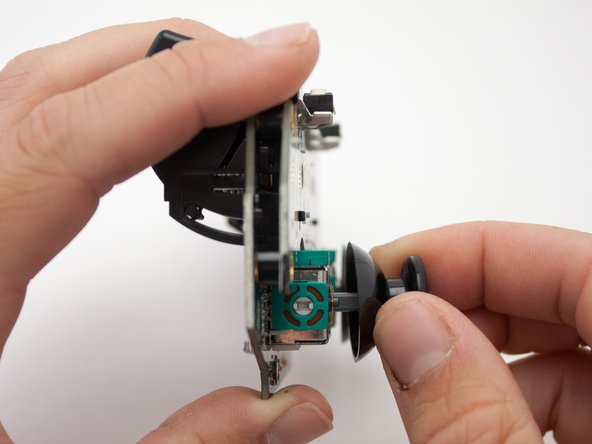
- Now back to the logic board. Flip the board so the joysticks are facing you. Firmly pull each joystick straight out, away from the board, to remove.
- To separate the two boards, gently pull them apart.
- There is a 30 pin connector between the boards above the left joystick. Keep the boards parallel when pulling them apart to avoid breaking any of the pins. Take similar care when putting them back together.
- That's everything you can disassemble without desoldering anything. Well done!