Sony Handycam HDR-CX580V Motherboard Replacement
ID: 87910
Description: This guide will help to locate and remove the...
Steps:
- Locate the slider labeled "BATT" and pull it back from the battery with your thumb.
- At this point, you should be able to remove the battery by simply lifting it from the camera.
- The camera provided for guide-creation did not include a battery. However, the battery position should be the same.
- Use the Phillips #00 head to remove the following 5.5mm screws on the left-hand side.
- Use the Phillips #00 head to remove the following 5.5mm screws on the empty battery socket.
- Use the Phillips #00 head to remove the following 5.5mm screws on the bottom.
- Fold back the hinging panel on the top of the camera located near the lens.
- Use the Phillips #00 head to remove the following 5.5mm screws on the top under the hinging panel.
- Slide back the cover for the DC and A/V ports on the right-hand side.
- Use the Phillips #00 head to remove the following 5.5mm screws underneath the cover and on the right-hand side.
- Use the plastic opener tool to loosen the casing on the bottom and the right-hand side.
- At this point, the right-hand side should simply come off, although it will still be connected with internal wiring.
- Be delicate with the wiring still attached to the side casing until you have access to removing them later.
- Carefully remove the bottom casing with your fingers.
- Be careful not to loose the small metal stand-mount pieces that lay underneath the casing.
- Look at the right side of the camera (the side with the recording button) while holding back the detached casing.
- Use the Phillips #00 head to remove the following 5.5mm screws near the recording button.
- Use the curved tweezers to carefully detach the blue ribbon cable connector from the body of the camera.
- The recording button and its blue ribbon cable connector should become detached from the body, but remain connected to the top casing.
- Pull off the top casing by lightly grabbing either side and pulling towards the back of the camera.
- Use the Phillips #00 head to remove the following 5.5mm screws on the inside of the top casing.
- Carefully remove the metal frame from the top casing.
- You are now free to remove the recording button, as well as its connection strip.
- Use the Phillips #00 head to remove the following 5.5mm screws on the right-hand side near the lens.
- Use the Phillips #00 head to remove the following 5.5mm screws on the top near the lens.
- Carefully pop off the casing strip on the camera's left-hand side near the lens.
- Use the Phillips #00 head to remove the following 5.5mm screws underneath the casing strip.
- Carefully pull the lens cover and shutter assembly off of the front of the camera.
- Do not pull the the wires out too strongly. Be sure to remove them from their base where they attach to the camera's body.
- Use the Phillips #00 head to remove the following 5.5mm screws on the lens shell.
- Carefully remove the lens from the body of the camera.
- Make sure to avoid touching the lens itself directly in order to prevent scratches or dirtying.
- To begin removing the metal casing, use the Phillips #00 head to remove the following 5.5mm screws.
- Hold the camera so you can see the motherboard on its bottom.
- With a pair of straight tweezers, carefully remove the hanging panel by the following bundled cable connectors and ribbon cable connector attached to the motherboard.
- At this point, the side panel that has been hanging should now be removed and placed to the side.
- The camcorder's chip and part of the motherboard should naturally fall off at this point and should carefully be removed and placed to the side.
- Use the Phillips #00 head to remove the following 5.5mm screws from the side of the motherboard.
- Use the Phillips #00 head to remove the following 5.5mm screws and remove the lens compartment by carefully pulling it out of the metal casing.
- Do not pull the lens compartment too hard.
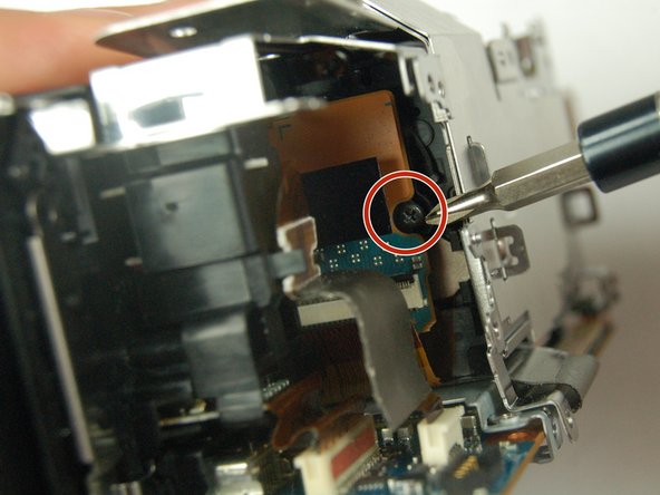
- Use the Phillips #00 head to remove the 5.5mm screw inside the metal casing.
- This screw may be hidden under the black strip inside the camera's body. If so, carefully move it aside with the pair of straight tweezers.
- Using a pair of tweezers, remove the ribbon cable connector attached to the metal casing and the motherboard.
- Using a pair of tweezers, remove the following ribbon cable connectors to remove the motherboard from the camcorder.
- Carefully remove the motherboard by hand.
- It should be relatively easy to remove if everything is removed properly.