Dell Photo Printer 540 Mother Board Replacement
ID: 8845
Description: In this repair guide you will be able to...
Steps:
- Rotate the photo printer so that the bottom of the case faces upward.
- Use a Phillips #2 screwdriver to remove the three 5.65 mm screws on the bottom panel of the case in a counter-clockwise fashion.
- Rotate the device so that it is upright again. Under the LCD Panel there is a 9.62 mm screw, unscrew using a Phillips #2 screwdriver.
- Remove the back panel of the case by pulling directly back.
- Some carefully applied force may be required to remove this part.
- Rotate the photo printer so that the bottom panel faces up once again. Now lift off the bottom panel of the case to access all internal components.
- Finally remove the side panel with the ink-cartridge door by holding the right side and pulling backwards with the left side.
- Caution! The side panel is held in by tabs; don't break these.
- Carefully remove the inner components of the device by lifting the inner components up and out of the casing.
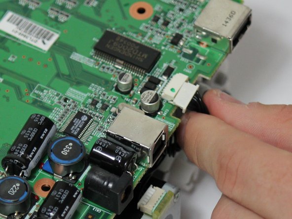
- Locate the red and black cable that is connecting the fan to the top of the logic board.
- Carefully, remove the red and black cable from the logic board by pulling gently in order to isolate the cooling fan from the device.
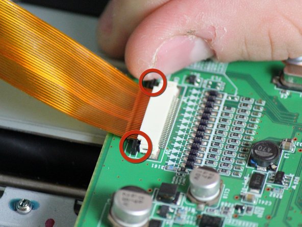
- Locate the data ribbon that connects the LCD panel to the mother board.
- Loosen the fasteners next to the ribbon by carefully pushing them away from the white ribbon holder.
- Once the fasteners are loosened the ribbon should easily slide away from the motherboard.
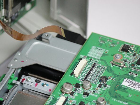
- Locate the clips with multi-colored wires that connect the motherboard to the printing unit.
- Disconnect both of them by gently pulling them away from the motherboard.
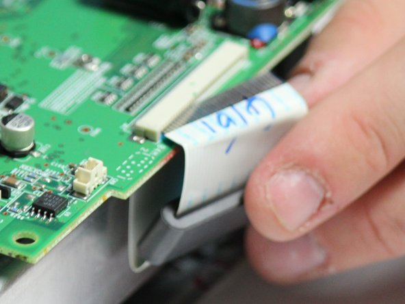
- Locate the white ribbon that connects the motherboard to the printing feed.
- Disconnect the ribbon by gently pulling the ribbon away from the motherboard.
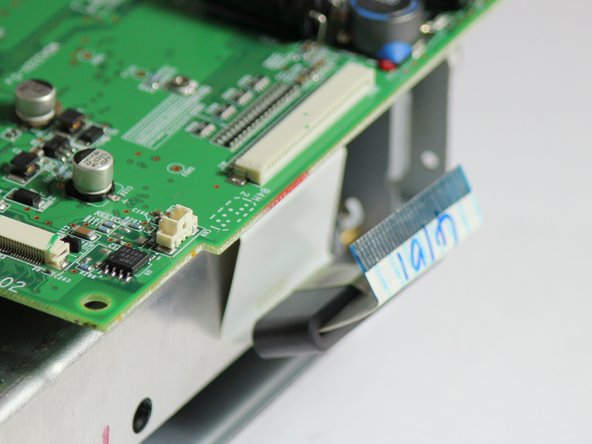
- The mother board has changed orientation. Notice the new orientation based on the white data ribbon we removed in the previous step.
- Locate the black data ribbon that connects the mother board to the printing motors.
- Disconnect it from the logic board, by gently pulling the wire away from the mother board.
- Now unscrew the three screws 7.89mm (counter-clockwise) using a Phillips #1 screwdriver.
- Once screws and ribbons are disconnected, you can pull mother board away from the printing unit.