Fujifilm X20 - On-/Off-Switch Repair
ID: 95426
Description: My X20's on-/off-switch mechanism, integrated...
Steps:
- Before you start remove batterie and SD-card!
- Take notes of all screw's positions! The best way to do that is to use a magnetic project mat.
- I removed the rubber covering completely to find all screws, but if you know the positions you can leave most rubber on and just remove it at the edges to access the screws. The rubber will stick well again after the repair but is very difficult to reattach after complete removal.
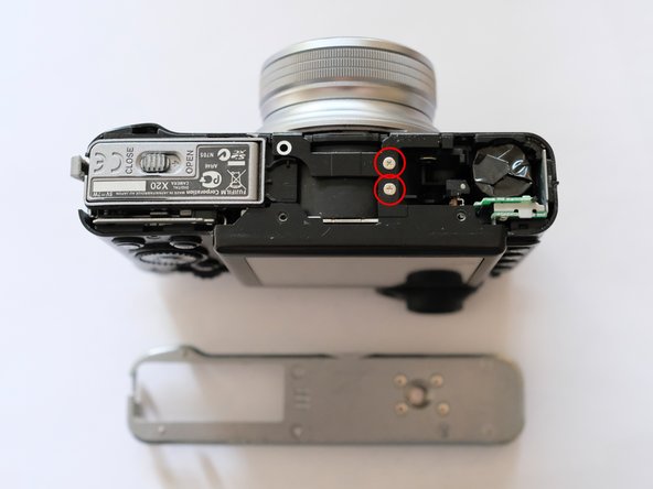
- Remove all screws marked red, the screws with green marks can stay in for now.
- Almost all screws are cross headed, except for one T2 size torx screw.
- Remove all screws marked red.
- Before you open the camera make sure you are electrically ground to earth. The best way to ensure that is to work with ESD-rated equipment such as wristband, mat and special srew-driver. Electrical discharge into the cameras electronics will lead to severe damage!
- Remove all screws marked red, the screws with green marks can stay in for now.
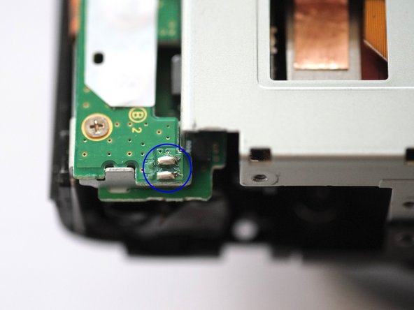
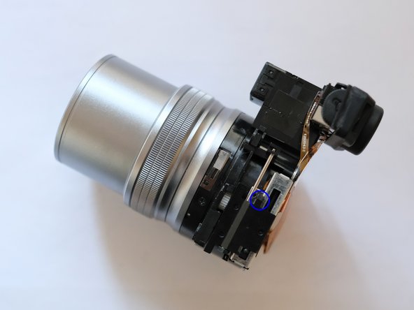
- After opening the bottom plate you will see the speaker on the position marked with a blue circle. In my case the cable detached trying to remove it, but since I never used the speaker I didn't care. You will need to find another way around it if you want to keep the speaker, shouldn't be to difficult now that you know how the next steps look like.
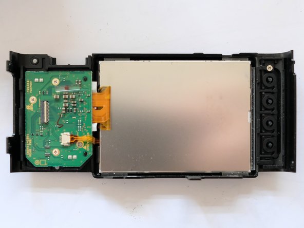
- Detach cable marked red opening a little bar on the switch to detach the backplate with screen.
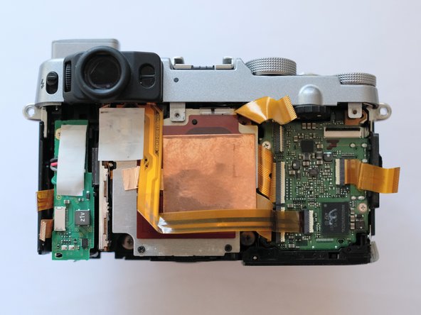
- Remove cables and screws on left side to remove the little PCB, that will enable to remove the metal cover.
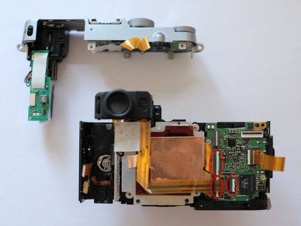
- In third image the blue circle marks the solder points the little speaker is attached to, shouldn't need to desolder I think.
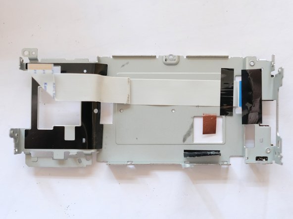
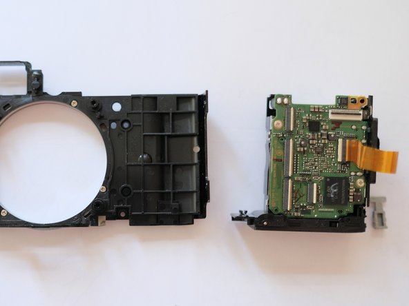
- The little PCB can be taken of the cable, also screws to be removed to detach the metal cover. The metal cover is attached to another cable on it's back.
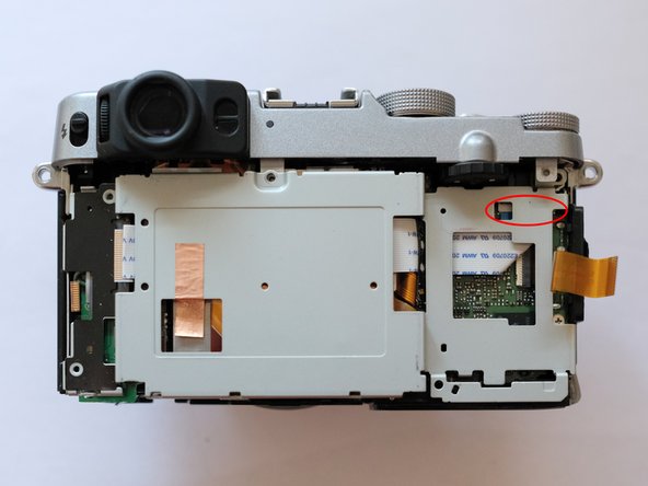
- To cables to be removed to detach the top bit of the camera, the flash unit including the capacitor can remain attached to the top section.
- WARNING: Be carefull with the flash unit capacitor, risk of very high voltage!
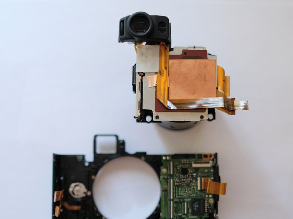
- 4 screws hold the lens/sensor unit in place.
- For the full teardown remove the two screws marked in red to take of the battery compartment.
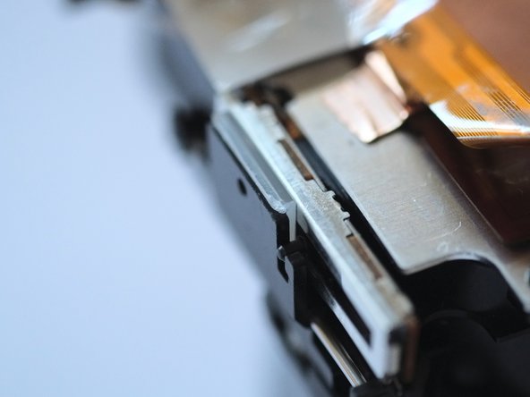
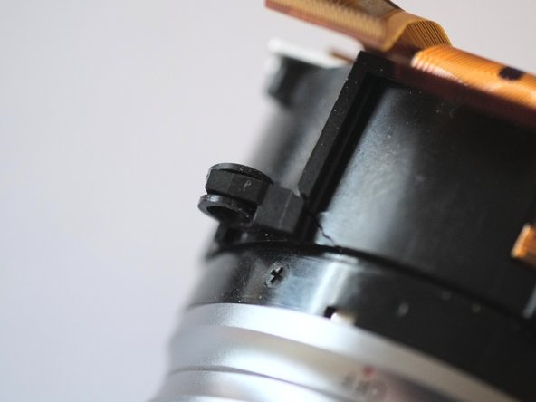
- Showing the mechanism that moves during zooming the lens and switching the camera on as well. Zooming the lens moves the black slider along the metal rail and activates the on-switch sitting inside. That works via a small white gearwheel that is connected to the black slider. The wheel also tells the camera electronics the current zoom position.
- In my case the black slider could tilt towards the rails, disconnecting the white gearwheel and therefore all electronic functions of the zoom mechanism.
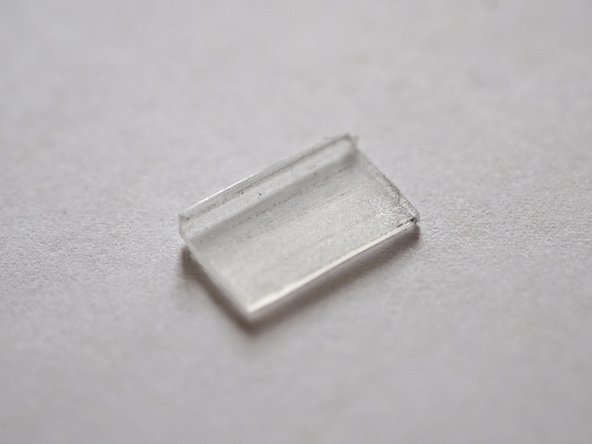
- To fix that I glued the bit of plastic onto the backside of the black slider, preventing it from tilting towards the rail. Before fixing the slider position make sure it’s in the right position to show the exact focal range later in camera.
- I found that the lens must have been knocked at some point since one of the lens fixing points were broken off (I assuming that must have broken the switch as well, maybe at the position marked blue in step 9 image 2).
- To fix this I reattached the fixing point using superglue.
- Re-assembled the camera working my way backwards through the steps, it is working fine now. Good luck!