Logitech Harmony Smart Keyboard Key Printed Circuit Board (PCB) Replacement
ID: 98971
Description: This is a replacement guide for the Logitech...
Steps:
- Turn keyboard over to the backside.
- Press and slide up on the upper battery latch, using both thumbs.
- Remove the two AA batteries and set them aside.
- Unscrew all five 4.0 mm screws, using Phillips #1 screwdriver.
- Peel off the center sticker to reveal two hidden 4.0 mm screws.
- Unscrew these two screws with a Phillips #1 screwdriver.
- Lift both top left and top right rubber stickers halfway, using the sharp end of the plastic spudger.
- Unscrew a total of two 4.0 mm screws, under the rubber stickers, using a Phillips #1 screwdriver.
- Unscrew the top center 4.0 mm screw, in the battery compartment, using the Phillips #1 screwdriver.
- Now, you should have a total of ten 4.0 mm screws set aside.
- Wedge the flat end of the spudger between the back panel and front panel.
- Slide the flat end of the spudger from right to left to pry the two panels apart.
- Separate the back panel from the front panel completely, using both hands.
- A white ribbon flex cable will remain connected to both panels.
- Pull the panels apart slowly and gently, or the white ribbon flex cable may be unsafely removed.
- Grip the lower end of the ribbon flex cable (white band) using your thumb and index finger.
- Then slide the strip out toward yourself in a scooping motion.
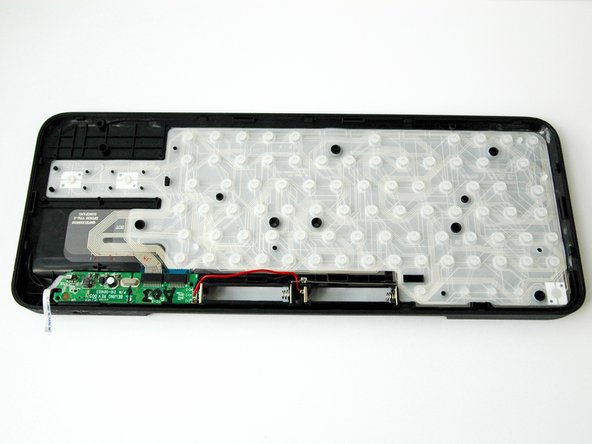
- Now, you should have two completely separated panel pieces.
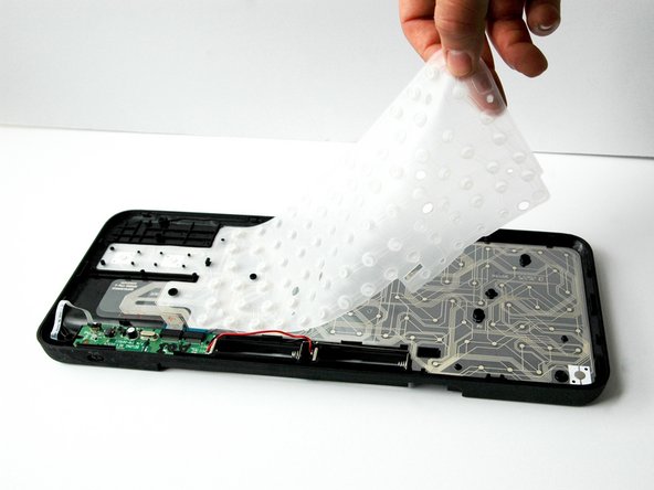
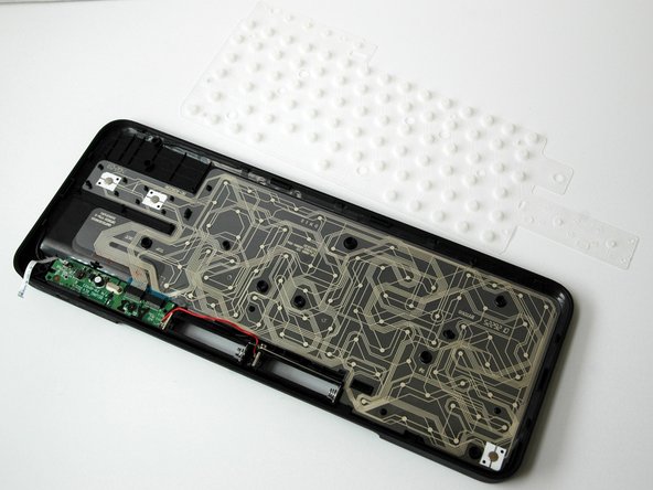
- Lift and remove the white rubber sheet that lays over the keyboard pet flexible PCB.
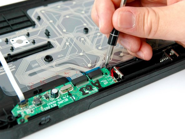
- Unscrew the two 4.0 mm screws on either side of the green card using a Phillips #1 screwdriver.
- Lift the green card up using the flat end of the plastic spudger.
- Grip and lift the keyboard PCB up and out.
- The battery wires will remain connected.
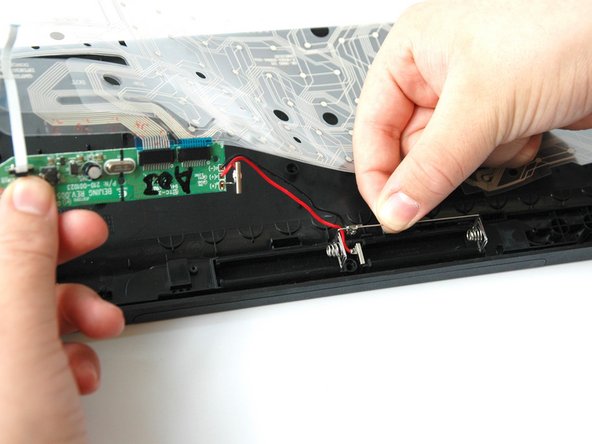
- Grip and lift the battery wire bar out of the battery compartment, using your thumb and index finger.
- Pinch your precision tweezers and wedge the battery clamp up.
- Lift the entire keyboard PCB out of the panel.
- The keyboard PCB will remain connected to the green card.
- Slide your index finger into the slot under the right blue tab.
- Pinch and pull the right blue tab away from the green card.
- Pinch and pull the left blue tab away from the green card.