Sony Vaio Tap 21 SVT212A11L Speaker Assembly Replacement
ID: 98995
Description: Use this guide to replace the speakers on a...
Steps:
- Insert the plastic opening tool at an angle into the grill and lift the tab by applying force down and to the left as you are lifting it out of place.
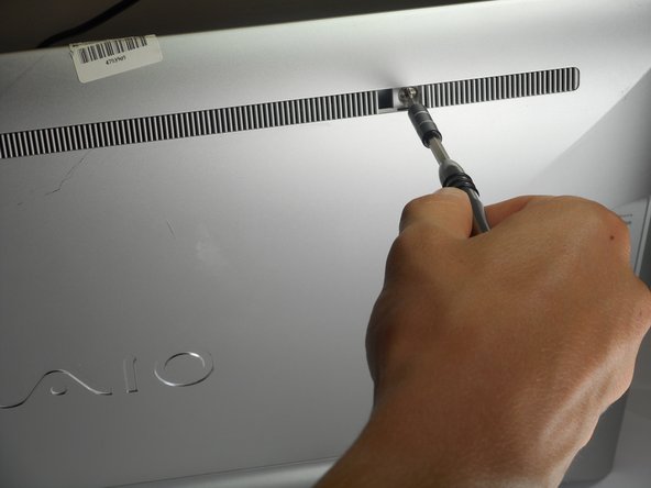
- Use your plastic opening tool to remove the right plastic tab blocking the screw mounts behind the device.
- The plastic tab is located on a plastic stretch of grill running along the upper half of the back of the device.
- You can find the tab looking for a solid fill within the grill. The tab is solid within the slits.
- Insert the plastic opening tool at an angle into the grill and lift the tab by applying force down and to the left as you are lifting it out of place.
- Use your plastic opening tool to remove the right plastic tab blocking the screw mounts behind the device.
- The plastic tab is located on a plastic stretch of grill running along the upper half of the back of the device.
- You can find the tab looking for a solid fill within the grill. The tab is solid within the slits.
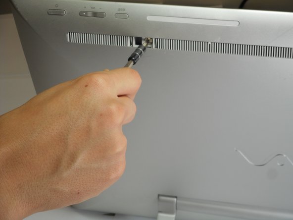
- Remove the two 5mm screws on the back of the device using a JIS 0 screwdriver.
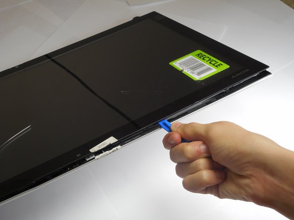
- Face the screen of the device upwards.
- Gently un-clip the screen around the four sides of the body with the plastic opening tool.
- Use an up-down motion.
- It would be easier to do this if the device is fully rested flat by pushing the device down. It should rest on the stand.
- Lift the screen gently from the top of the device.
- Make sure to lift the screen from the same side the screws were removed.
- Slowly and gently lay the screen on its face.
- It's important that the cables are not damaged while doing this process. Ensure as you lay the screen on its face any cables are carefully moved insuring no stress is applied on the cables.
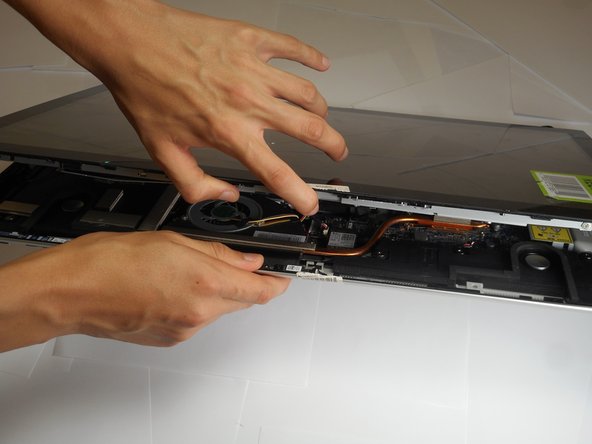
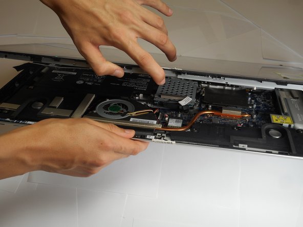
- Remove four 9mm screws from the fan attachment located on the motherboard with a Phillips #1 screwdriver.
- Remove two 6mm screws located on both sides of the fan component using a Phillips #1 screwdriver.
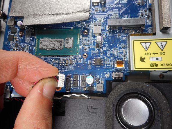
- Un-click the cables attached to the face of the motherboard.
- These cables are secured tight in their place so remove them with a firm grip.
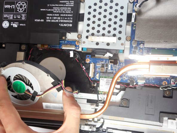
- Firmly lift the fan from the surface.
- The fan is held tight in its place so lift it with slightly more force.
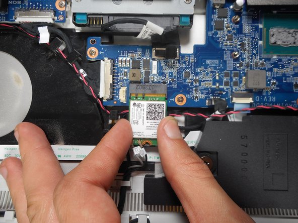
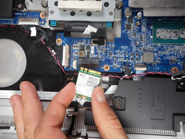
- Use a JIS 00 screwdriver to remove a 5mm screw from the wireless receiver.
- The wireless receiver is a chip located in the area between the motherboard, fan, and one of the speakers.
- Gently detach the wireless receiver and place it somewhere it does not obstruct the speaker assembly.
- Remove a total of four 8mm screws with the Phillips #2 screwdriver from the speaker located below the motherboard.
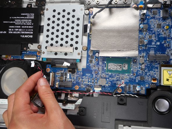
- Detach the cables that connect from the speaker to the motherboard.
- The cables attached to the motherboard are held firmly in place so pull them with slightly more force to release them.
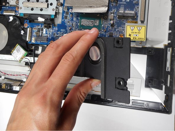
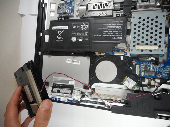
- Slowly lift the speaker from its base.
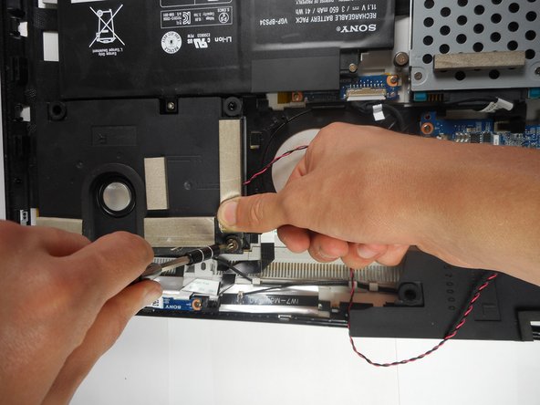
- Remove four 8mm screws from the speaker below the battery with a Phillips #2 screwdriver.
- One of the four screws is located under a foam pad on one of the corners of the speaker. Lift the foam pad to remove the screw.
- Carefully lift the speaker from its base.
- To fully remove the speaker assembly, remove the red and black intertwined cables that connect both speakers.