M3D Micro Data and Power Port Replacement
ID: 99127
Description: If the 3D printer is not responding when...
Steps:
- Place pressure on the central print bed and simultaneously pull up on the outer perimeter of the 3D printer. The cube shaped enclosure will lift up.
- Remove the print bed cover and locate the four screws holding the print bed to the base of the unit. Remove the four 9.5 mm screws using the 3.5 Hex head from the bit kit.
- Lifting the print bed reveals the motherboard that controls the unit. This is the hardware that allows the printer to connect to the computer. The port on the left is the data and the port on the right is the power input.
- The ports are primarily soldered on to the board but are additionally secured using glue. Use the sharp metal spudger tool to gently pry apart the glue surrounding the ports.
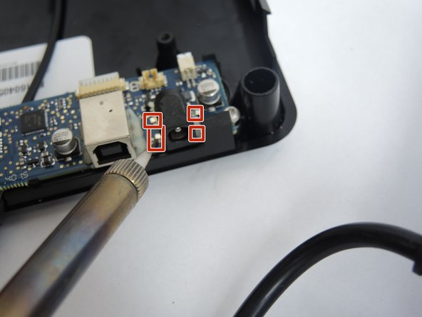
- To remove the charging port grasp the port with a pair of pliers and use a soldering iron to desolder the joints at the red marks while carefully pulling away with the pliers.
- To replace the power port, match the four contact points on the board to the new port and carefully solder the components together.
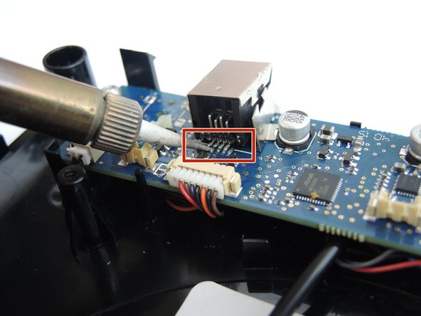
- To replace the USB data port, follow the same procedure as Step 5. The contact pins for the data port are on the back. The red marker indicates the four contact pins that must be matched up and carefully soldered on.