HP Pavilion 14-q020nr Wi-Fi Card Replacement
ID: 99172
Description: Wi-Fi cards are often replaced to gain faster...
Steps:
- Turn the laptop over.
- Remove all nine 3mm screws on back panel with a Phillips Head 1 driver.
- Pry off the four rubber bumpers, located at the top corners and center of the back panel, off with a pair of tweezers.
- Bumpers are delicate and can be easily ripped.
- Unscrew the four 3mm screws under the bumpers using a Phillips Head 1 screwdriver.
- Flip the laptop right side up and open the clamshell.
- Starting at the bottom right corner, slide the opening tool into the crevice between the blue and silver panels.
- Carefully pry the top casing up around the edges, moving counterclockwise.
- Keep the tool steady throughout, as prying in a rough manner can break the casing.
- You will hear audible clicking sounds as the clips connecting the two halves disconnect from each other.
- Close the laptop and orient it on its side (clamshell hinge up), carefully holding it steady to ensure its safety.
- Insert the opening tool inside of the hinge and pry with an even amount of force to disconnect the keyboard panel from the fan grate.
- Reorient the laptop in an upright fashion and open the clamshell.
- If needed, continue to pry the silver keyboard panel from the rest of the hardware with minimal force.
- Slowly slide the silver keyboard panel towards you while lifting gently to separate the halves.
- The panel is still connected by a series of delicate connectors glued to the mainframe, so do not pull the panel right off.
- While keeping silver keyboard panel hovering above the laptop, locate the touchpad connector ribbon attached to both the silver panel and motherboard.
- With your finger, flip up the white clasp that holds the connector, releasing the connector ribbon.
- Unpeel the connector ribbon from its position on the motherboard.
- With your finger, flip up the white clasp that connects the larger keyboard connector to the motherboard, releasing the connector ribbon.
- Gently pull the connector ribbon from the clasp.
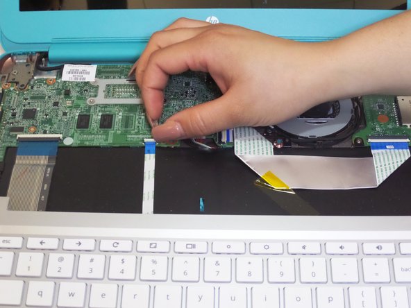
- Lift the keyboard panel up and away from the CPU, completely revealing the mainframe.
- With the internal hardware exposed, disconnect the battery cable from the motherboard.
- If tightly fastened, gently wiggle the plug out of the jack.
- Remove the three 4mm screws around the perimeter of the battery pack with a Phillips Head 1 screwdriver.
- Flip up the two white clasps that hold the connector ribbon to the battery to release the ribbon.
- Remove the 'motherboard to USB board' connector ribbon from its place.
- Detach the speaker cable from its fastener on the motherboard by pulling it out with your fingers or using a spudger.
- Using your fingers, gently pry out the two L-shaped speaker panels from between the external casing and battery pack.
- Be sure to apply an evenly distributed upwards force on the speaker when lifting it out
- Both speaker components (located adjacent to each other) will remain connected by a red cable after removal
- Lift out battery pack.
- Remove the two Wi-Fi antenna cables that are attached to the Wi-Fi card by pulling them up.
- Using your fingers, pull the cooling fan cable from its fastener on the motherboard
- Remove the 3mm screw that holds down the Wifi mini-PCI card using a Phillips Head 1 driver.
- Remove the three 3mm screws that hold the cooling fan in place using a Phillips Head 1 driver.
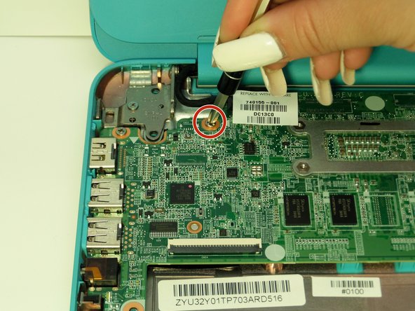
- In the upper right hand corner of the device, remove the 6mm screw holding the PCB board in place by using a Phillips Head 1.
- Remove the three 3mm screws from the surface of the motherboard using a Phillips Head 1.
- Carefully lift the motherboard up towards the screen as if it was hinged on one side.
- To prevent possible scratching, cover the screen with a cloth.
- Using your fingers, pull the Wi-Fi card located on the right side of the detached motherboard out of its place.