HP Pavilion Wave 600-a010 Fan Replacement
ID: 99190
Description: This guide will help give direction to properly...
Steps:
- Remove the three rubber footings by prying from the bottom cover using the plastic opening tool.
- Remove the three 24 mm screws from the bottom cover using a Phillips #2 screwdriver.
- Remove the bottom cover by lifting it up from chassis.
- Remove the three wires connecting the outer cover and front I/O port to the internal components (front usb and auxiliary assembly).
- Remove the outer cover by gently pulling apart and pulling away from the chassis.
- Remove rear I/O bezel using plastic opening tool to pry apart the four clips holding the I/O bezel to the chassis.
- Remove all other remaining cables from unit using the plastic opening tool to carefully pry apart the connections.
- Remove the HDD by first using the Phillips #2 screwdriver to remove the four 23 mm screws holding together the assembly and then pulling the HDD out of the chassis.
- Remove the three 24 mm screws that connect the top cover to the chasis inside the HDD compartment using theTorx #15 screwdriver (an extension and torque lever might be useful).
- Disconnect the microphone computer chip from the internal components by first peeling away the black adhesive holding the wires to the chassis and gently pulling the chip and wires from its connection.
- Remove the top bezel from the unit using a Torx Head #15 screwdriver to remove three 24 mm screws and a Phillips Head #00 screwdriver to remove the single 24 mm screw around the outside edge of the chassis.
- Remove the top chassis cover from the main chassis using the Torx Head #15 screwdriver to remove the nine 24 mm screws and then use the metal prying tool to pry the top chassis cover from the clips holding it to the main chassis and lift carefully away from internal components.
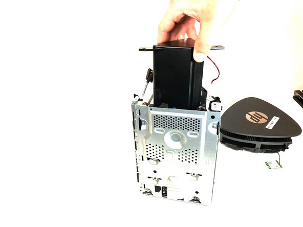
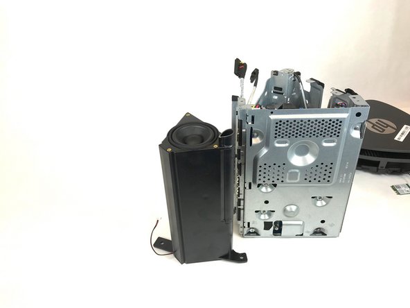
- Remove the speaker by removing three 24 mm screws using the Torx Head #15 screwdriver and carefully lifting up and out from internal components.
- Remove the memory cover by removing the single 24 mm screw holding it to the main chassis using the Torx Head #15 screwdriver and sliding it up and out of its locking clips.
- Remove the memory circuit board by pushing down on the white tabs on either side of the memory circuit board until it slightly pops up.
- Lift the memory circuit board up and out of its connection, and out of the main chassis.
- Remove the fan by removing the three 23 mm silver screws that hold the fan to the chassis using a Phillips Head #0 screwdriver.
- Remove the fan from the chassis by sliding it up and out of the the clips holding the fan to the chassis.