HP Spectre 13 4003dx x360 Motherboard Replacement
ID: 105118
Description: This guide will give you step-by-step...
Steps:
- Before you begin, be sure to turn off your laptop and discharge the battery down to 25%.
- Turn the computer upside down.
- Use the T5 Torx Screwdriver to remove the eight 3.3 mm screws.
- Make sure to use the magnetic project mat to help you keep track of the small screws.
- Use an opening tool to pry up and loosen the back case from the laptop.
- If the back case doesn't loosen easily, there may be screws hidden underneath the rubber feet. Carefully pry a foot up and remove any hidden screws.
- Remove the back case.
- Remove the four 2mm Phillips #00 screws securing the battery.
- The screw locations are marked by small white arrows on the battery.
- Peel off the adhesive on the left side of the battery holding the speaker wire down.
- Move the battery slightly to gain access to the battery plug, located on the left edge of the battery.
- Carefully unplug the battery by pulling the connector towards the battery.
- Pull parallel to the battery, not straight up.
- Remove the battery.
- It is normal for your battery to flex and bend a bit where the wider section meets the narrower section.
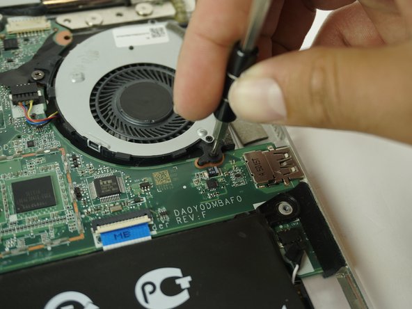
- Remove the two 2mm Phillips #00 screws from the fan.
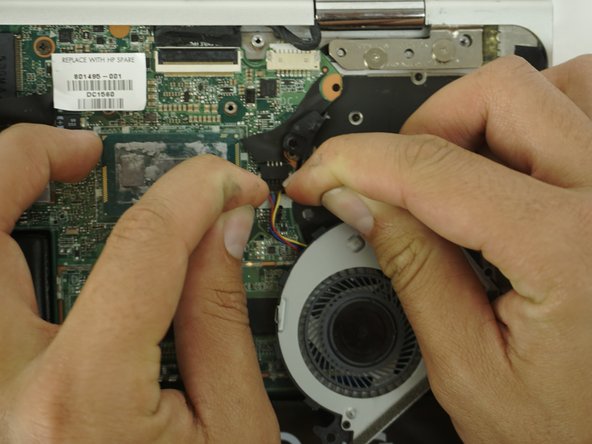
- Disconnect the fan from the motherboard.
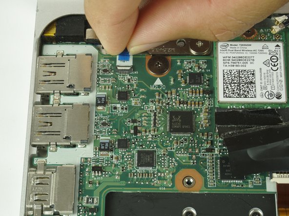
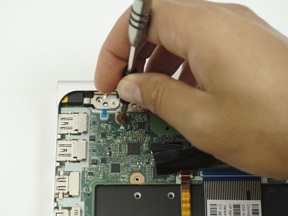
- Using a plastic opening tool, disconnect the antenna wires from the WiFi card.
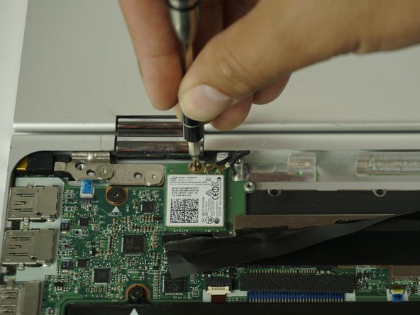
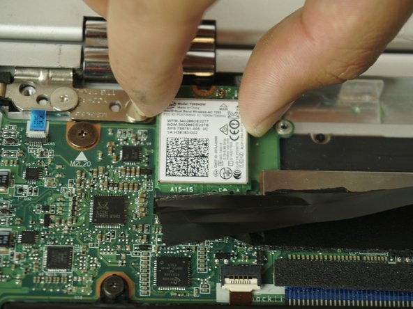
- Remove the single Phillips #00 screw from the WiFi card.
- Slide the module up until it is completely removed.
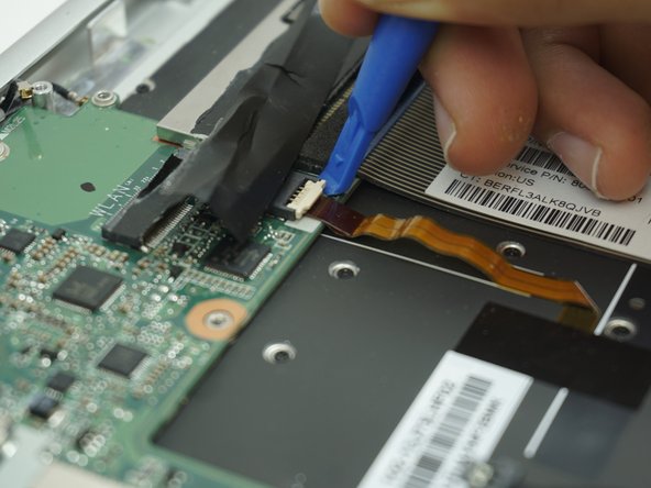
- Use a plastic opening tool to flip up the retaining flap on the ribbon cable ZIF socket.
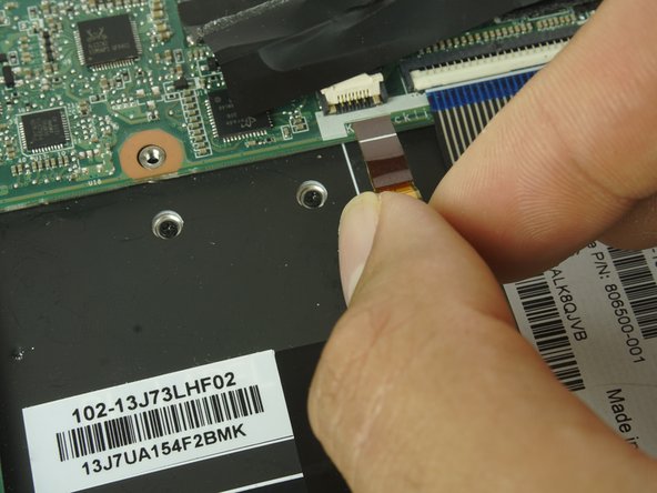
- Pull the ribbon cable out of the ZIF connector.
- Using two plastic opening tools, Disconnect the right speaker cable from the motherboard.
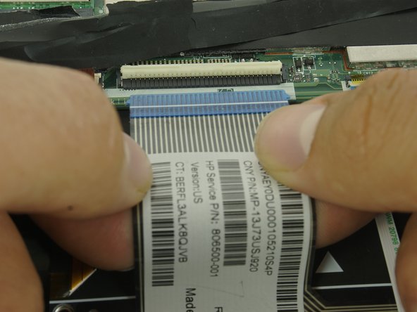
- Identify the ZIF connector that connects the keyboard to the back light as shown in the image.
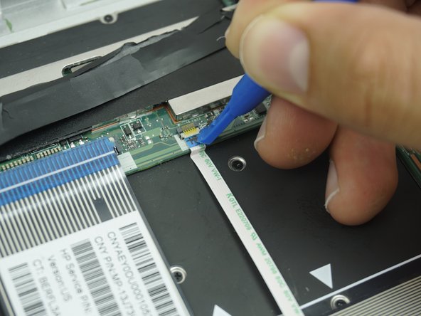
- Using a plastic opening tool, lift the locking bar on the ZIF connector that connects the keyboard back light to the motherboard.
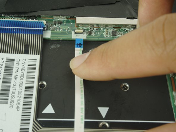
- Gently pull the cable out.
- Gently peel back the tape on the locking bar of the keyboard connector.
- Using a plastic opening tool, pull up on the locking bar.
- Gently pull the cable out.
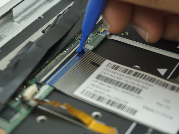
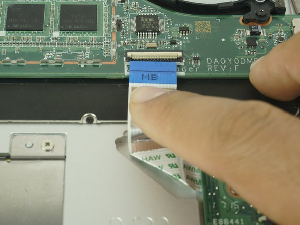
- Identify the touch pad ZIF cable as shown in the image.
- Using a plastic opening tool, Gently lift up the locking bar on the touch pad ZIF.
- Gently slide the cable out.
- Using a plastic opening tool, Lift the locking bar on the card reader ZIF connector.
- Gently slide the cable out.
- Using two plastic opening tools, Disconnect the left speaker cable.
- Using two plastic opening tools, Unplug the power cable connector.
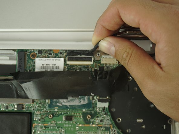
- Using a plastic opening tool, Lift the locking bar on the display connector.
- Grip the black tape and pull up to unplug.
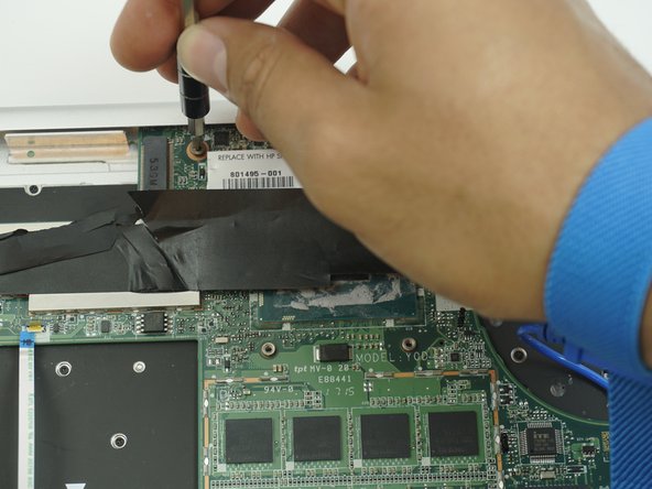
- Remove the 3.5mm Phillips #00 screw securing the motherboard to the top cover.
- Remove the 2mm Phillips #00 screw securing the motherboard to the top cover.
- Remove the motherboard from the alignment pins on the top cover.