Asus Zenbook UX21e LCD Screen Replacement
ID: 108487
Description: For the LCD screen, initially, follow the...
Steps:
- Using a T4 Torx screwdriver, unscrew the ten screws lining the bottom cover. Then, proceed to remove the bottom cover by sliding it out parallel toward the back of the computer.
- There are two length of screws. Eight screws are 3mm and two are 5mm. The two 5mm screws always go into the two center holes along the back edge.
- Using an iFixit opening tool and your other hand, gently lift the connector up from the tape wrapped around the connector wires and pry the connector from the motherboard.
- Remove the battery by unscrewing the five 3mm screws using a Phillips #1 screwdriver.
- One at each corner and one in the center.
- Lift the battery directly up and remove it from the device.
- Remove the tape wrapped around the LCD connector by pulling it towards the screen hinges of the computer.
- Disconnect the LCD connector by sliding it out of its socket.
- Using a Phillis #1 screwdriver, remove the four 3 mm screws at the screen hinges to allow the screen to pull off of the device.
- If the hinges are too hard to remove by hand, use the leverage of the keyboard to slide them out.
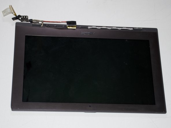
- Remove the plastic vent from screen by using an iFixit opening tool to pry the vent from the screen edge.
- Exercise caution when prying the vent off. Too much deflection can cause the vent to snap. Work both ends.
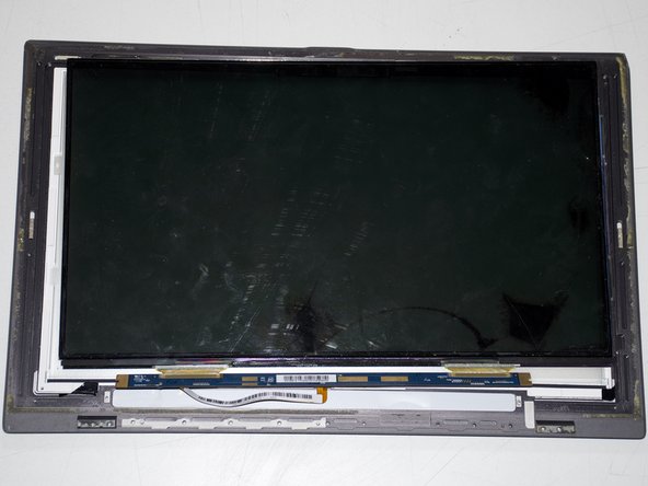
- Remove the nine 3 mm screws along the base of the screen using a Phillips #1 screwdriver.
- Remove four 5 mm screws along the two internal hinges using a Phillips #1 screwdriver.
- These four screws are hidden by cables and need to be removed in order to see the screws.
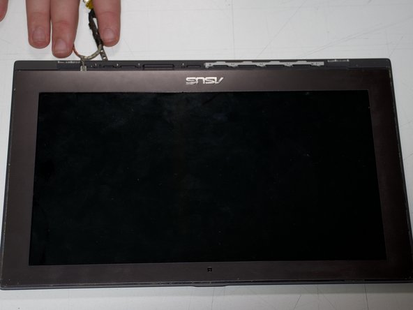
- Remove the rubber o-ring (the thin rubber strip that lines the bezel edge) by peeling it off.
- Heat the bezel using any heating tool such as a hair dryer, etc.
- Use a metal spudger to help rip off the bezel and the rubber-o-ring.
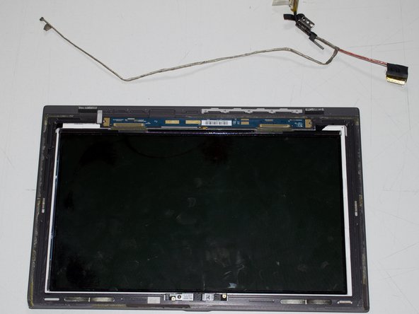
- Disconnect the LCD connector from the screen housing by pulling the connector.
- Unscrew the two 2 mmm screws that line the screen control board using a Phillips #1 screwdriver.
- Remove the cable connecting the screen housing to the control board by pulling the cable.