MacBook Pro 13" Function Keys 2017 Display Assembly Replacement
ID: 117328
Description: Use this guide to replace the display assembly...
Steps:
- Before starting this procedure, you must disable your Mac's Auto Boot feature. Auto Boot powers on your Mac when you open the lid, and may be accidentally triggered during disassembly. Use this guide or follow the abbreviated instructions below to disable Auto Boot. This command may not work on all Macs.
- Power on your Mac and launch Terminal.
- Copy and paste the following command (or type it exactly) into Terminal:
- sudo nvram AutoBoot=%00
- Press [return]. If prompted, enter your administrator password and press [return] again. Note: Your return key may also be labeled ⏎ or "enter."
- You can now safely power down your Mac and open the bottom case, without it accidentally powering on.
- When your repair is complete and your Mac is successfully reassembled, re-enable Auto Boot with the following command:
- sudo nvram AutoBoot=%03
- Before proceeding, unplug and power down your MacBook. Close the display and lay it on a soft surface, top-side down.
- Use a P5 Pentalobe driver to remove the six screws securing the lower case:
- Two 6.2 mm screws
- Two 5.3 mm screws
- Two 3.4 mm screws
- Throughout this repair, keep track of each screw and make sure it goes back exactly where it came from to avoid damaging your device.
- Apply a suction handle to the lower case near the front-center area of the MacBook Pro.
- Lift the suction handle to create a slight separation between the lower case and the chassis.
- Insert one corner of an opening pick into the space between the lower case and the chassis.
- Slide the opening pick around the nearest corner and halfway up the side of the case.
- This releases the first of the hidden clips securing the lower case to the chassis. You should feel and hear the clip pop free.
- Repeat the previous step on the opposite side, sliding your opening pick under the lower case and up the side to pop the second clip free.
- Insert your opening pick once again under the front edge of the lower case, near one of the two centermost screw holes.
- Give the pick a firm twist to pop free the third clip securing the lower case to the chassis.
- Repeat this procedure near the other of the two centermost screw holes, popping the fourth clip free.
- Pull the lower case firmly towards the front of the MacBook (away from the hinge area) to separate the last of the clips securing the lower case.
- It may help to pull first at one corner, then the other.
- This may require a lot of force.
- Remove the lower case.
- Carefully peel up the large piece of tape covering the battery connector, on the edge of the logic board nearest the battery.
- Remove the tape.
- Gently peel back the small piece of tape covering the battery board data cable connector.
- The tape is integrated into the ribbon cable and will not detach completely. Simply peel it back enough to access the connector.
- Use the tip of a spudger to flip up the small black locking tab securing the cable in its connector.
- Disconnect the battery board data cable by sliding it out from its socket.
- Slide parallel to the logic board, in the direction of the cable.
- Fold the battery board data cable back and out of the way.
- If you're replacing your battery, you may need to completely remove and transfer this cable to your new battery. Disconnect both ends and carefully remove the cable. During installation, be careful not to install it upside-down or backwards—note the orientation in the photos.
- Use a T5 Torx driver to remove the 3.7 mm pancake screw securing the battery power connector.
- Use a spudger to gently lift the battery power connector, disconnecting the battery.
- Lift the connector high enough so that it stays separated from its socket. If it accidentally makes contact during the course of your repair, it could damage your MacBook Pro.
- Remove the four 1.9 mm T3 Torx screws securing the plastic covers on top of the display hinges.
- Remove both plastic hinge covers.
- Remove the two 2.9 mm T3 Torx screws securing the aluminum cover on top of the main display cable.
- Remove the cover.
- Remove the two 1.7 mm T3 Torx screws securing the aluminum cover on top of the display cable flex connector.
- Remove the cover.
- Pry the display board flex cable straight up from its socket to disconnect it from the display board.
- Remove the four 1.5 mm T3 Torx screws securing the two aluminum covers on top of the two display cables.
- Use a pair of tweezers to remove the two aluminium covers.
- Remove the two 3.3 mm T5 Torx screws (one from each side) securing the antenna cable assembly.
- Also remove the two 4.1 mm T5 Torx screws (one from each side).
- Remove the twelve 1.1 mm P2 pentalobe screws (six from each side) securing the rest of the antenna cable assembly.
- Carefully disconnect the two antenna coax cables by prying them straight up from the logic board.
- Slide your tweezers or spudger underneath each cable until it's near the socket, and then gently twist or pry up to disconnect it.
- To reconnect each cable, align the connector directly over its socket, and then press down so it snaps into place.
- Remove the 2.8 mm T5 Torx screw securing the two antenna coax cables to the main board.
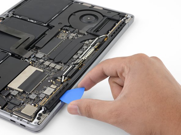
- Use an opening pick to lever out the antenna cable assembly in the areas shown.
- Don't slide the opening pick from side to side, as there are two display cables in the way that may be damaged.
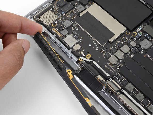
- Carefully remove the antenna assembly, while simultaneously feeding the antenna cable bundle through the hole in the chassis.
- Remove the antenna cable assembly.
- During reassembly, gently pinch the cable bundle together and guide through the hole in the chassis into the correct position on the board. If needed, use your tools to help guide it through, but don't force it.
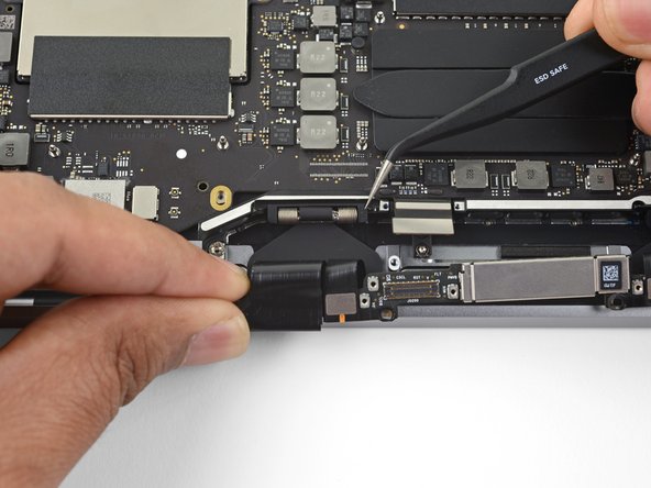
- Remove the four 3.9 mm T3 Torx screws securing the cover springs on the two display cables.
- Grab the left side of the display cable assembly and pull it towards the bottom end of the MacBook and away from the cover spring.
- Use a pair of tweezers to pull the cover spring on the display cable out of its recess.
- Repeat this step with the right cover spring.
- Fully open the screen and stand your MacBook Pro up on one side.
- While steadying the MacBook pro with your free hand, remove the three T8 Torx screws from the lower display hinge.
- Remove the remaining three T8 Torx screws from the upper display bracket.
- Keep a firm grip on both the screen and main body of the MacBook Pro. Either half can fall unexpectedly during this step.
- Push both halves of the MacBook Pro together so that the hinge brackets can be lifted clear of their recesses in the chassis.
- Push the main body of the MacBook Pro away from you while pulling the screen toward you to separate it.
- Remove the display/screen assembly, being careful not to snag it on any cables.
- During reassembly, ensure the display cable assembly lies on the correct side of the main body before refastening the hinge bolts.
- Be sure to confirm that both connectors on either side of the display cable assembly are fully seated, as these may have come loose during the disassembly process.