HP ElitePad 1000 G2 Motherboard Replacement
ID: 125074
Description: If your ElitePad is failing to turn on follow...
Steps:
- Before disassembling the tablet: make sure the tablet is off, disconnect the power cord from the tablet, and disconnect all external devices from the tablet.
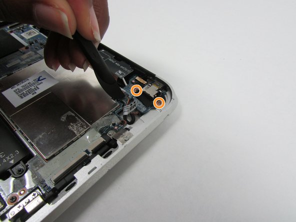
- Using a Phillips #00 screwdriver, remove the two Phillips PM 1.4×3.2mm screws located next to the charging port.
- Place the suction cup on the lower right corner of the tablet display glass, making sure to place the suction cup inside the edges of the border of the display glass.
- Insert a plastic pick in between the display and the tablet case. Then use a plastic removal tool to separate the display further.
- Pull on the suction cup while using the prying tool to separate the display from the tablet.
- Gently lift the display from the tablet in order to avoid damaging the cables.
- To disconnect the cables, use the spudger tool to gently pull back on the black tab located on the side of the connector while gently pulling the cable.
- Release the zero insertion force (ZIF) connector to which the TouchScreen cable is attached, and then disconnect the TouchScreen cable from the system board.
- Release the ZIF connector to which the display cable is attached, and then disconnect the display cable from the system board.
- Remove the display from the tablet.
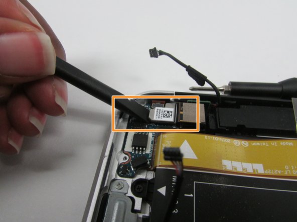
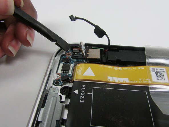
- Locate the NFC antenna.
- Release the ZIF connector to which the NFC antenna cable is attached.
- To disconnect the cable, use the plastic prying tool to gently push on the tab located on the side of the connector.
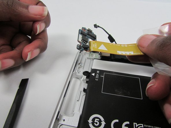
- Detach the NFC antenna from the surface of the system board.
- The NFC antenna is attached to the system board with double-sided adhesive.
- Remove the NFC antenna.
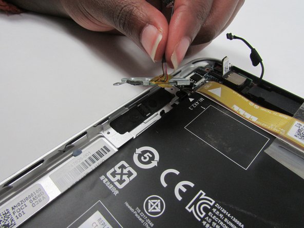
- Locate the power button board and attached ribbon cable.
- Locate the volume button board.
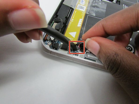
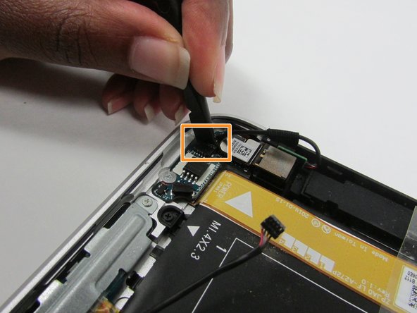
- Disconnect the volume button board cable from the power button board.
- Disconnect the left microphone cable from the power button board.
- For both of these connectors, there's a thin seam in the middle. To disconnect, wedge your tool in between the seam and firmly, but carefully push.
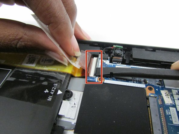
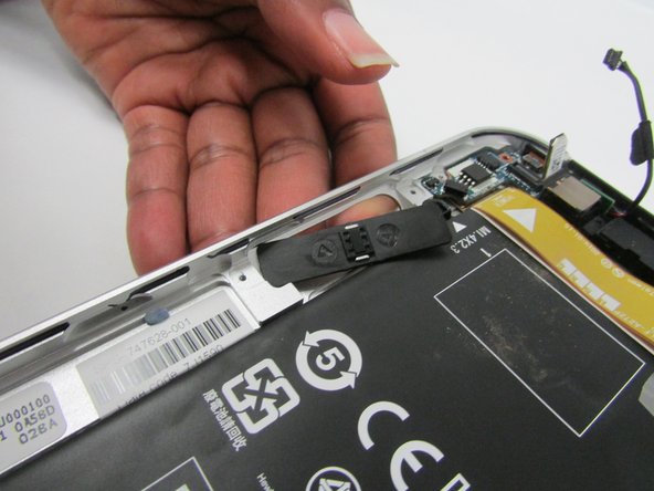
- Lift the clear tape which is attached to the power button board cable and the motherboard.
- Release the ZIF connector to which the power button board cable is attached.
- Detach the power button board cable from the surface of the battery by pulling away from the connector.
- The power button board cable is attached to the battery with double-sided adhesive.
- Remove the Phillips PM1.3×2.0mm broad head screw and the Phillips PM1.3×2.0mm screw that secure the power button board to the bottom cover.
- Gently push upwards on the tab
- Remove the power button board and cable.
- Remove the two Phillips PM1.5×2.0mm screws that secure the volume button board to the bottom cover.
- Remove the volume button board and cable.
- Locate the audio jack board.
- Disconnect audio jack board cable from the motherboard.
- Remove the two Phillips PM 1.3x2.0mm screws that secure the audio jack board from the housing.
- Remove the audio jack board.
- Locate the power button board ribbon cable.
- Locate the battery to motherboard connector.
- Lift the clear tape attached to the power button board ribbon cable.
- Disconnect the ZIF connector by using a plastic removal tool to gently pull up on the black tab.
- Lift the power button board ribbon cable up and away so that it doesn't get in the way of the battery during removal.
- Disconnect the battery to system board connector by pushing gently on it with a plastic pry tool and then pull it away from the system board.
- Using a philips 00 screw driver take out the six Phillips PM1.3×2.0mm screws
- Carefully lift the battery away from the bottom cover.
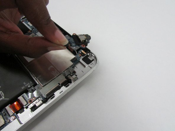
- Release the webcam from the housing.
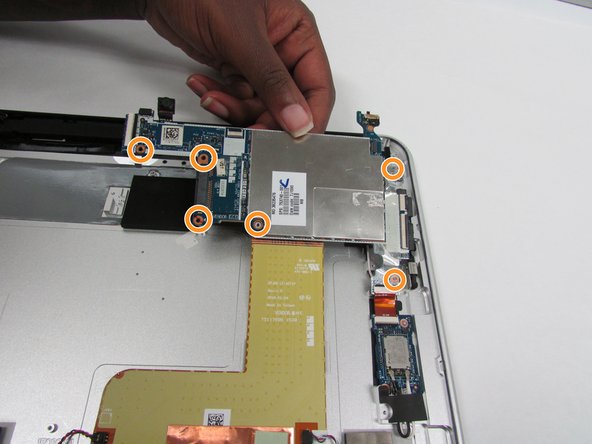
- Remove the six Phillips PM 1.3 x 2.0mm screws that secure the board to the bottom cover.
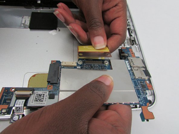
- Carefully lift the mother board from the top by the camera and reveal the back side of the board.
- With the backside of the motherboard exposed remove the two Phillips 1.3 mm screws.
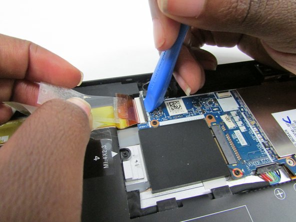
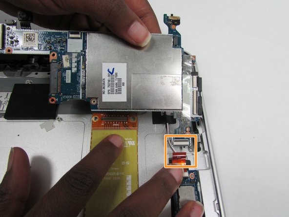
- Disconnect the ribbon connector on the back of the board.
- Remove ribbon connector that connects to the WLAN module.
- Remove the motherboard.