Teardown of IBM ThinkPad i Series 1200
ID: 127670
Description: This guide shows how to disassemble the IBM...
Steps:
- Before beginning, ensure the notebook is powered off.
- Unplug the power cord.
- To remove it, slide the two switches in such a way that it is unlocked, as shown in the picture, and then remove it.
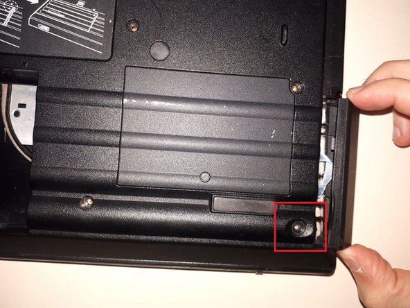
- Remove the screw in the lower corner.
- Remove the "cover" of the disk.
- Pull the "hook" that is attached to the disc to remove it.
- Remove the indicated screw from the backside of the notebook.
- Take off the cover that protects the RAM memory.
- Open the screen and lay it off the side in a flat manner.
- Remove the indicated screws on the backside of the PC.
- Slide the keyboard down so that the covers from above aren't blocked and as so we will be able to remove them more easily.
- Don't pull too hard as this can cause the flex cables to break.
- Disconnect the two ribbon cables that are located on the underside of the keyboard.
- The back up battery will be connected on the upper middle part.
- Remove the three indicated screws from the backside.
- It is to be note that these screws are located under protective rubber caps.
- Remove the RAM compartment.
- Remove the two indicated screws.
- Remove the metal protector that is found above the plate.
- Remove the Ethernet card.
- Careful as there's a cable connected that can be accidentally broken.
- Remove the indicated screws from the backside of the PC.
- Remove the optical drive by simply sliding it out.
- First, remove the plastic components indicated.
- These components are press-fitted, and thus we will have to remove them with care.
- Remove the two screws that are found after step one.
- Remove the plastic protector that is found on the upper part.
- Remove the two indicated screws.
- Proceed by removing the two connectors that are found there.
- Carefully start separating the display from the inferior side of our PC.
- Remove the plastic frame that surround the netbook.
- This component is press-fitted, so you have to remove it carefully so it doesn't break.
- Remove the metallic protector.
- Put aside the CPU cooler.
- Clean the fan and the old CPU paste.
- You have to use alcohol and a small tissue.
- Alcohol is to not be used on any other part that was that aforementioned.
- Place new thermic paste and start putting your PC back together.
- Once step 13 is completed.
- Remove the plastic covers that surround the display.
- It must be done with a guitar "pick" as the plastic covers could break or scratch.
- Remove the indicated screws that hold the led board.
- Remove the indicated screws that hold the metallic covering.
- Underneath you will find the inverter.
- Power supply connectors from motherboard to inverter.
- Data cables from motherboard to display.