HP Z2 Mini G3 Motherboard Replacement
ID: 130488
Description: The motherboard connects and powers HP Z2 Mini...
Steps:
- Turn the device so the back-side of the device is facing you.
- Be sure that the power is off and the A/C power cord has been disconnected before starting. Removing hardware while the power is on could damage the device or harm yourself.
- Components of the device are subject to static damage. Work on a hard, grounded surface to prevent damage to the workstation.
- Slide and hold the latch in the direction of the engraved arrow (to the right).
- While holding the latch, lift the access panel upwards and towards yourself and set it aside upside-down.
- Rotate the device so the front side is facing you (the side with the power button) and locate the CPU fan.
- Swing the fan upward, to a 90-degree angle.
- Carefully disconnect the CPU fan by pulling out the wires from the motherboard.
- Swing the fan back down and carefully unhook the CPU fan notches by pulling each tab away from the heat sink holes.
- Swing the fan up again and pull it out.
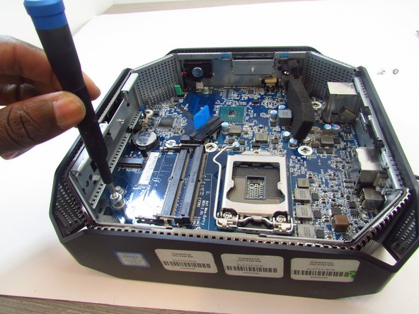
- Remove the 9mm Torx screw with a T15 Torx screwdriver to release the SSD assembly.
- Lift the assembly upwards to remove it.
- Pull the metal arm out from under the frame and lift it up. The frame should slide back from under the screw.
- Lift the frame upward to gain access to the processor
- Take note of a triangular mark on one of the corners of the processor and bracket it is mounted on. The triangles must be aligned together during reassembly.
- Grip the processor on each side, carefully lifting it up.
- Do not touch the underside of the processor. Doing so may damage the processor and prevent a connection to the motherboard.
- Be careful inserting the new processor. The connectors on the new one and the motherboard are fragile and damage easily.
- Remove the thermal sensor cable from the motherboard.
- Grab and lift the cable from the chassis to finish removing the thermal sensor.
- Some models may have a wireless LAN module installed under the GPU fan.
- In this case, use a T15 Torx screwdriver to remove the 9mm Torx screw from the module and take the component out.
- Unplug, then carefully detach the system speaker from the chassis by gripping the frame and pulling back.
- You do not need to remove the speaker from its frame.
- Use a T15 Torx screw driver to remove the 9mm and the two 16mm Torx head screws that secure the motherboard to the chassis.
- Slide the motherboard forward and to the left to clear it from chassis.
- Carefully pull and lift the motherboard out by holding on to the ports.