Honda 3000 Watt Inverter Generator EU3000IS1AWK Stator Replacement
ID: 136210
Description: This guide shows how to remove and replace the ...
Steps:
- Before you begin, make sure the generator is off and cool to the touch.
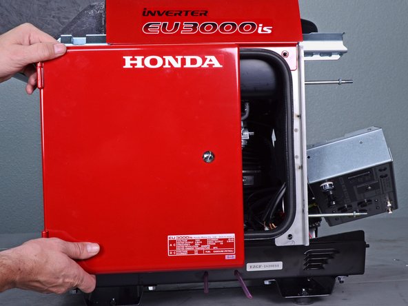
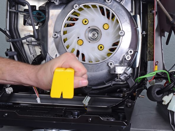
- Use a large flathead screwdriver to unlock the maintenance cover.
- Open the maintenance cover.
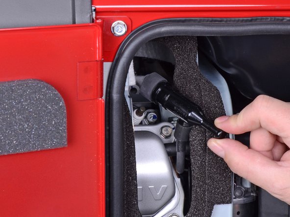
- Use a Phillips screwdriver to remove the screw securing the spark plug cover.
- Remove the spark plug cover.
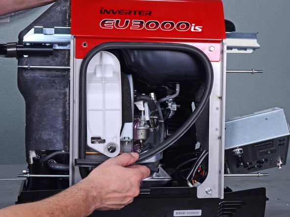
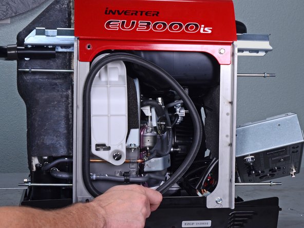
- Grab the plastic housing at the end of the spark plug wire.
- Pull firmly to disconnect the wire from the spark plug.
- Turn the fuel valve to the cutoff position.
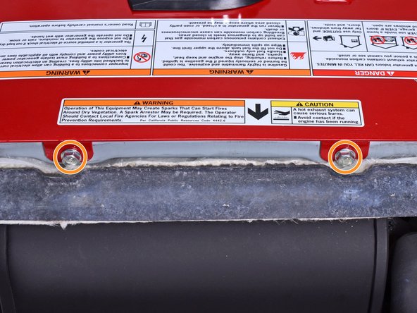
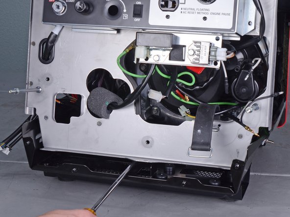
- Carefully tilt the generator to its side or back.
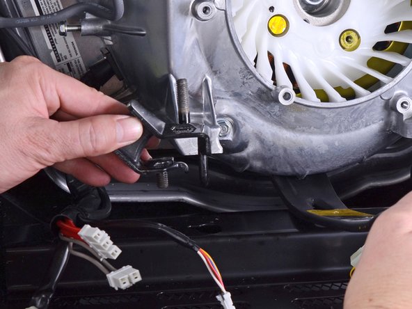
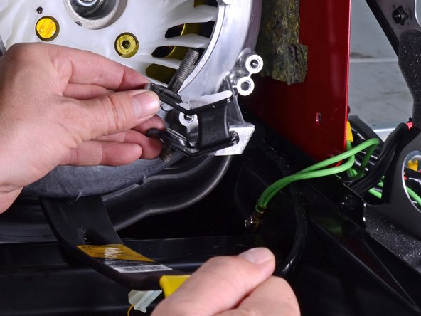
- Use a 10 mm socket to remove the two nuts securing the front bushing mounts to the bottom of the generator.
- Carefully tilt the generator back to an upright position.
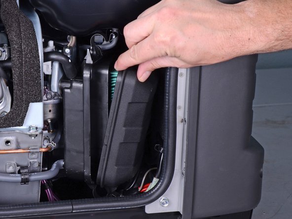
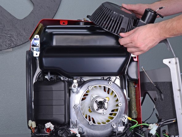
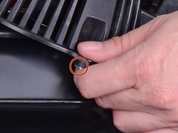
- Unlatch the four clips securing the air cleaner cover.
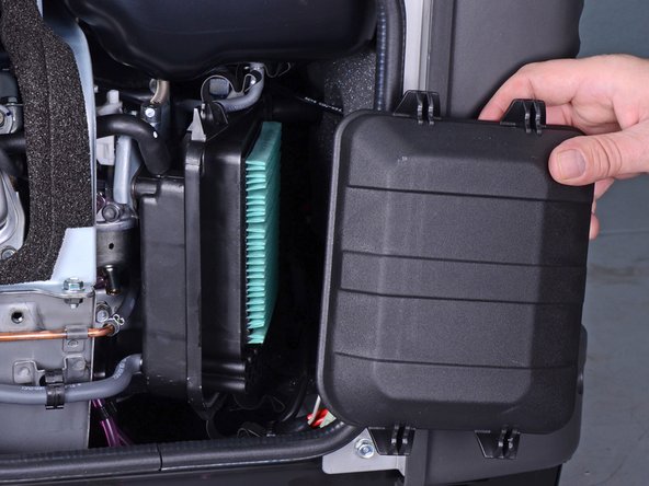
- Remove the air cleaner cover.
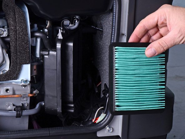
- Remove the air cleaner filter from the housing.
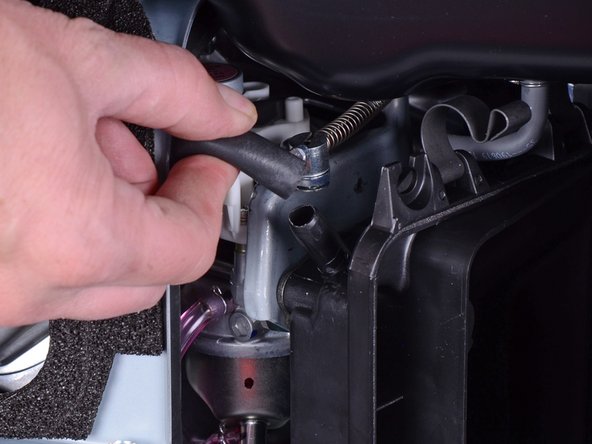
- Pull and disconnect the breather tube from the top corner of the air cleaner housing.
- Pull and disconnect the lower tube from the bottom corner of the air cleaner housing.
- Use a 10 mm socket to remove the three fasteners securing the air cleaner housing:
- Two 10 mm nuts
- During reassembly, tighten these nuts to 6.3 ft-lb (8.5 N-m).
- One 10 mm bolt
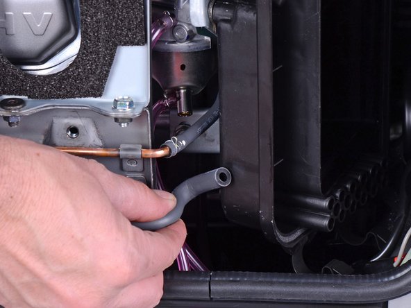
- Pull the housing out slightly from its recess.
- The housing still has tubes clipped to it.
- Use a flathead screwdriver to pry and unclip the tube from the air cleaner housing.
- Remove the air cleaner housing.
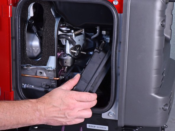
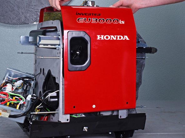
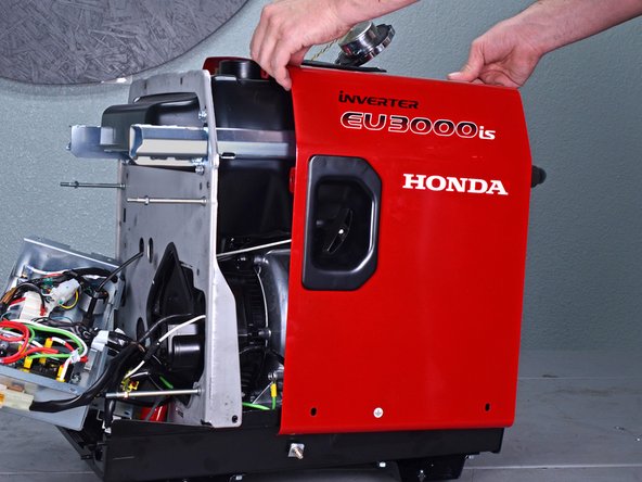
- Use a 10 mm socket to remove the four capped nuts securing the front cover.
- Remove the front cover.
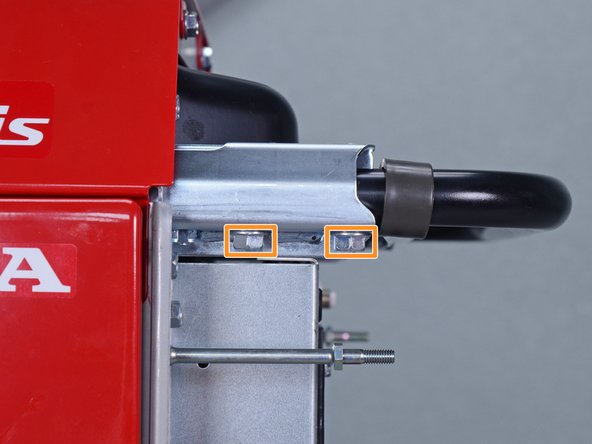
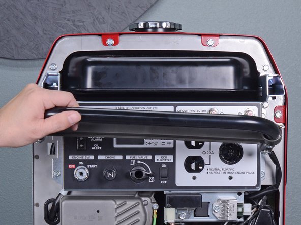
- Use a 10 mm socket to remove the four bolts securing the handle to the frame.
- Remove the handle.
- Use an 8 mm socket to disconnect the battery wires from the battery terminals.
- Disconnect the black negative cable first to prevent the risk of shorting the battery.
- During reassembly, connect the black negative cable first. Make sure you reconnect the wires in the correct polarity.
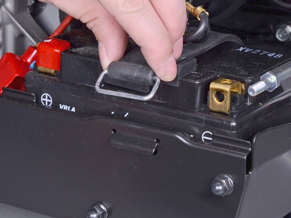
- Unclip the battery strap from the lower plate.
- Remove the battery.
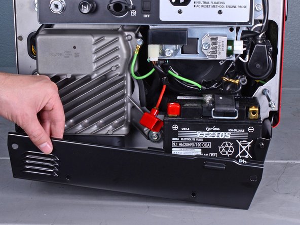
- Use a 10 mm socket to remove the four capped nuts securing the lower plate.
- Set these capped nuts apart. They look similar, but are smaller than the front cover nuts.
- Remove the lower plate.
- Insert a flathead screwdriver into the top of the brown fuse clip in order to release the fuse holder.
- Detach the fuse holder from the brown clip.
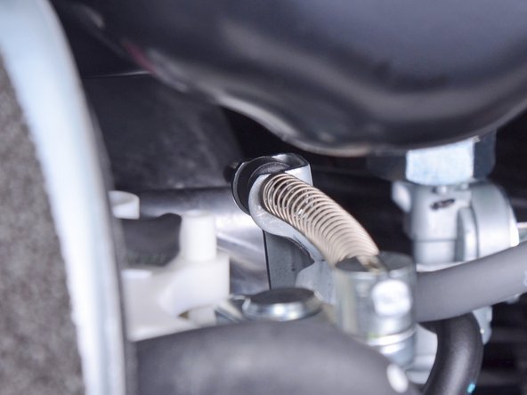
- Use pliers to lift and disconnect the choke cable from the choke stay.
- During reassembly, be sure to test the choke to ensure that it is properly connected.
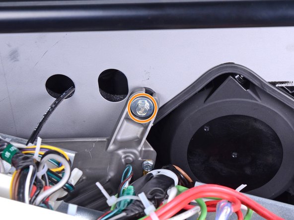
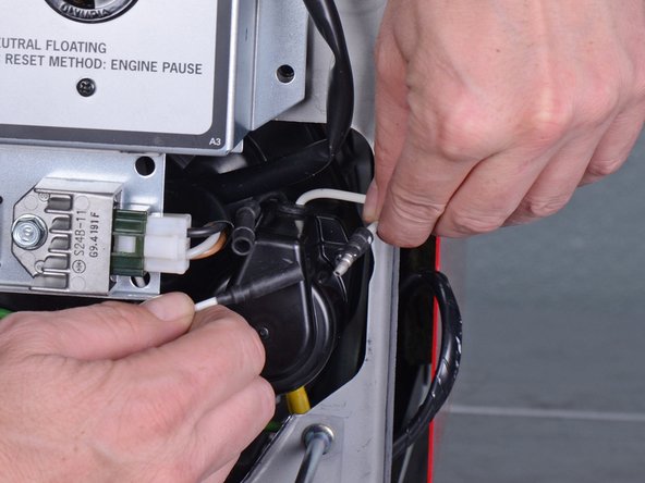
- Use a long shaft Phillips screwdriver to remove the deeply recessed screw securing the fuel cutoff switch.
- Be careful not to turn the fuel cutoff switch while you remove the screw.
- Remove the fuel cutoff switch.
- During reassembly, be sure to test the switch to ensure that it is properly installed.
- Use a 10 mm socket to remove the four bolts securing the control panel.
- Carefully tilt the control panel downwards.
- The control panel will still be connected to many wires and cables. Be careful not to strain any of the connected wires.
- Remove the following bolts securing the inverter:
- One 8 mm ground bolt
- Three 10 mm bolts (one behind the control panel)
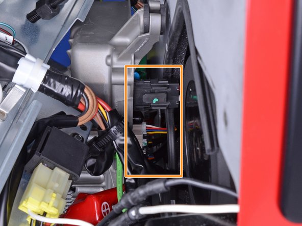
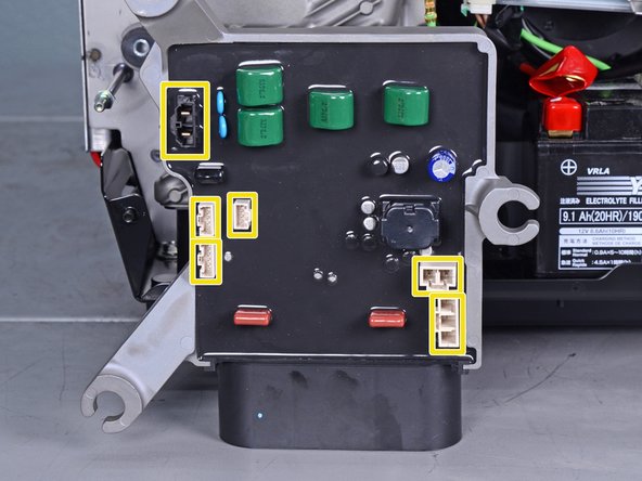
- Reach behind the inverter along the edges and disconnect the six connectors from the back of the inverter.
- All the connectors use locking tabs, so you will have to squeeze them in order to release them.
- The third image shows the locations of all six sockets on the inverter.
- Reassembly tip: Every socket on the inverter is different, so you can't plug something into the wrong place. Do not force the connectors into their sockets.
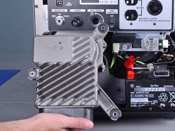
- Remove the inverter.
- If you are replacing the inverter and the replacement did not come with rubber mounts, follow the next two steps to transfer them over.
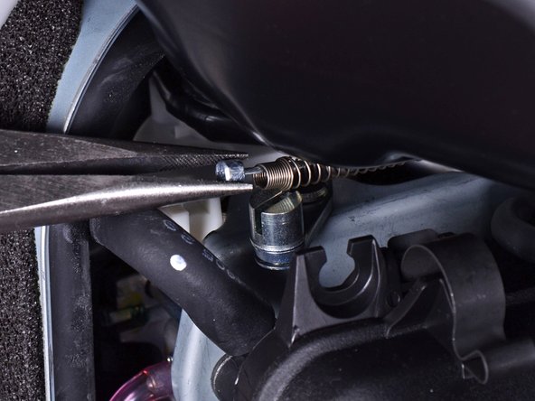
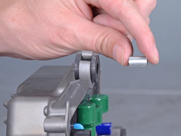
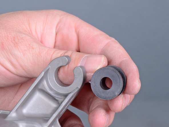
- Use a screwdriver to push the metal collar out of the center of the rubber mount.
- Squeeze the mount and remove it from the inverter.
- Repeat the procedure with the remaining mounts and transfer them to the replacement inverter.
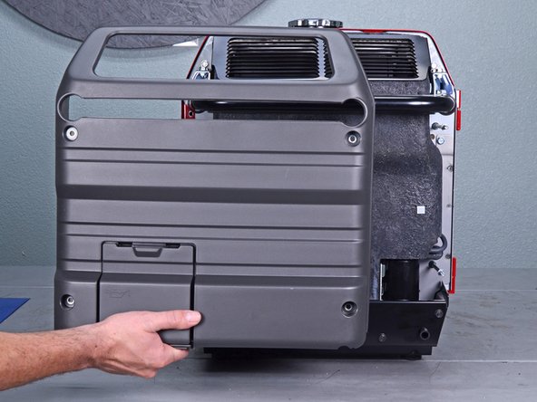
- Use a 10 mm socket to remove the four capped nuts securing the rear cover.
- Remove the rear cover.
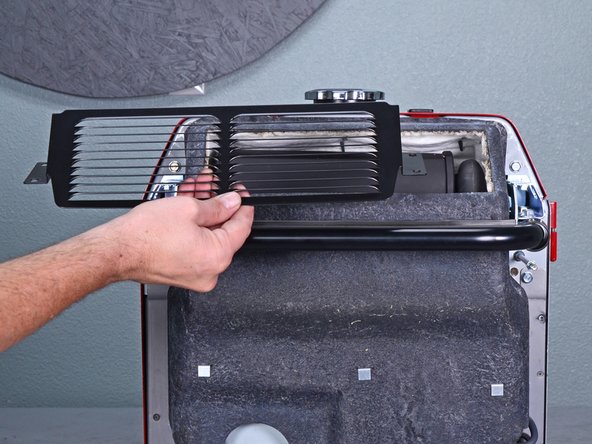
- Use a 10 mm socket to remove the four bolts securing the muffler protector.
- Remove the muffler protector.
- Pull the muffler shroud slightly away from the frame to access the top frame bolts.
- Use a 10 mm socket to remove the two bolts securing the top edge of the cover.
- Use a 10 mm socket to remove the three bolts securing the front edge of the cover.
- Use a 10 mm socket to remove the four bolts from the maintenance cover side.
- Remove the maintenance cover.
- Carefully peel the maintenance cover seal from the frame.
- Use an 8 mm socket to remove the two bolts securing the non-access side of the cover.
- Unscrew the gas cap.
- Lift the cover up slightly to free it from the frame and slide it back by a few inches.
- At this point, it may be helpful to temporarily re-attach the control panel back onto the front frame with some 10 mm bolts.
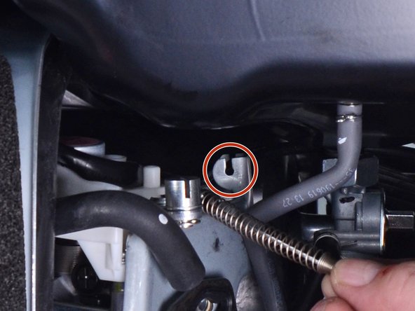
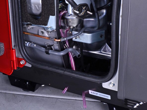
- Lift up and release the choke cable's rubber bushing from the choke stay.
- During reassembly, make sure that the choke cable's rubber bushing is properly seated on the choke stay.
- Use a 10 mm socket to remove the three frame bolts securing the bottom of the front frame.
- Use a 10 mm socket to remove the four bolts securing the top of the front frame.
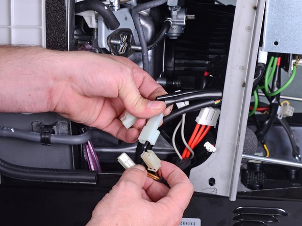
- Pull and disconnect the starter motor's black barrel and white barrel connectors.
- During reassembly, the wires should be reconnected to their respective colors.
- Unplug the two-wire oil switch connector.
- Unplug the four-wire regulator connector from the bottom edge of the control panel.
- Unplug the two winding connectors.
- These connectors all have brown wiring in black sleeves.
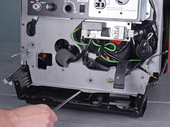
- Insert the edge of a large flathead screwdriver under the bottom edge of the front frame.
- Pry up and outward to release the bottom edge of the front frame.
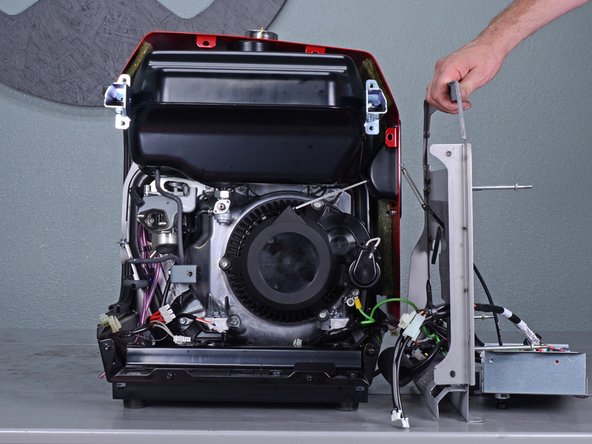
- Carefully swing the front frame to the right side of the generator.
- While the images show the control panel unbolted from the front frame, you can keep it bolted to the frame.
- The front frame is still connected to the generator by many wires. Be careful not to strain any wires.
- Use a 10 mm socket to remove the three bolts securing the recoil starter.
- Remove the recoil starter and move it out of the way.
- Be careful not to lose the metal collar in each of the recoil starter's bolt holes.
- Use a 10 mm socket to remove the two bolts securing the starter pulley.
- Remove the starter pulley.
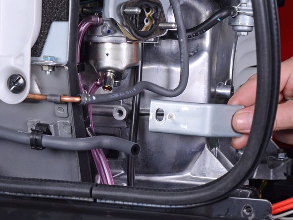
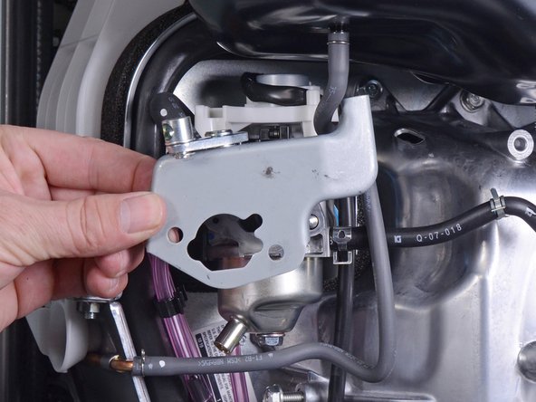
- Use a 10 mm socket to remove the bolt securing the air cleaner housing bracket.
- Remove the air cleaner housing bracket.
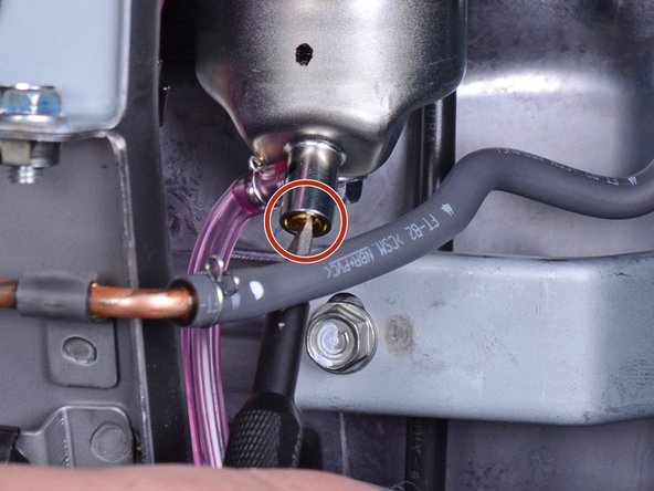
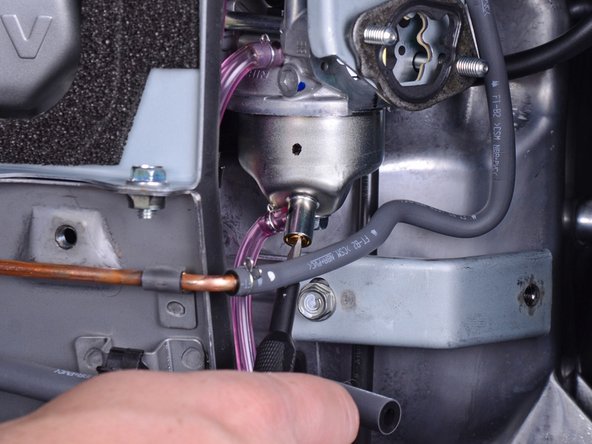
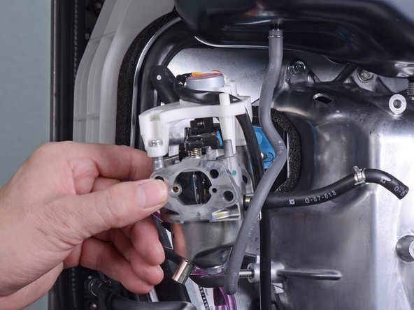
- Fuel may leak out when you disconnect this hose. Be ready to catch any spillage.
- Use pliers to squeeze and loosen the hose clamp securing the carburetor fuel line.
- Pull and disconnect the carburetor fuel line from the petcock assembly.
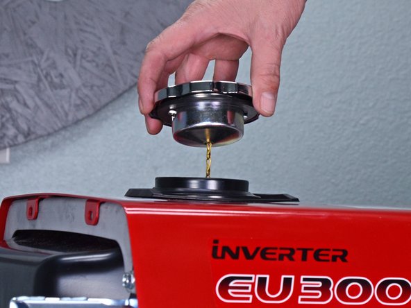
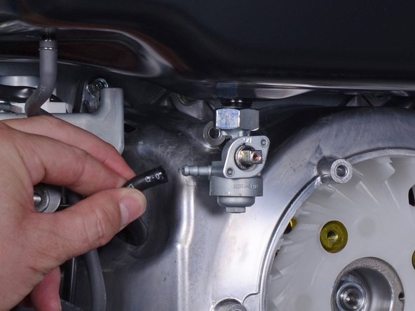
- Be sure to drain the fuel tank before you perform this step.
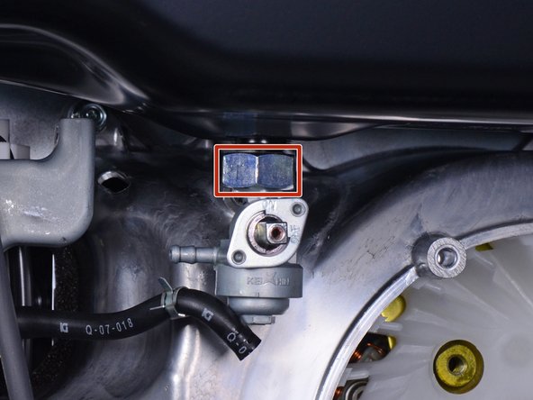
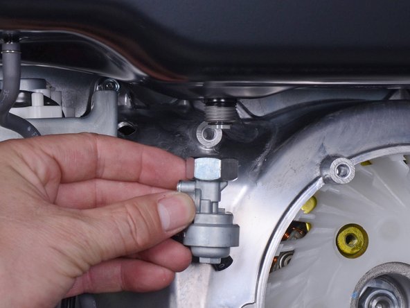
- Use a large crescent wrench to loosen the petcock assembly from the fuel tank.
- Residual fuel will leak out as you remove the petcock assembly. Be ready to catch any spillage.
- Remove the petcock assembly.
- Place a container below the carburetor drain tube to catch the excess fuel.
- The carburetor drain screw is located at the bottom of the carburetor.
- Use a flathead screwdriver to loosen the brass fuel drain screw until fuel begins to drain out of the carburetor.
- Once you drain the fuel bowl, re-tighten the fuel drain screw.
- Be sure to replace any gaskets that are torn or worn out.
- Remove the carburetor spacer gasket.
- Replacement part: Honda Spacer, Carburetor 16220-ZE1-020
- Remove the choke stay.
- Remove the air cleaner gasket.
- Replacement part: Honda Gasket, Air Cleaner 16269-ZE1-800
- Slide the carburetor off the mounting bolts.
- During reassembly, use the third photo as a reference for how to route the carburetor tubes.
- Disconnect the throttle control connector from the top of the carburetor.
- Unwrap the throttle control wires from the carburetor.
- Remove the carburetor.
- Remove the carburetor gasket.
- Replacement part: Honda Gasket, Carburetor 16221-ZH8-801
- Remove the carburetor insulator.
- If the carburetor insulator gasket is worn, remove and replace it.
- Replacement part: Honda Gasket, Insulator 16212-ZH8-800
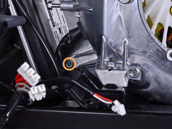
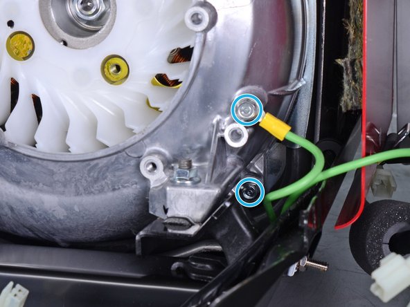
- Use a 10 mm socket to remove the seven bolts securing the fan cover:
- Four bolts on top
- One recessed bolt in the bottom left corner
- Two bolts in the bottom right corner
- During reassembly, be sure to reattach the ground wire.
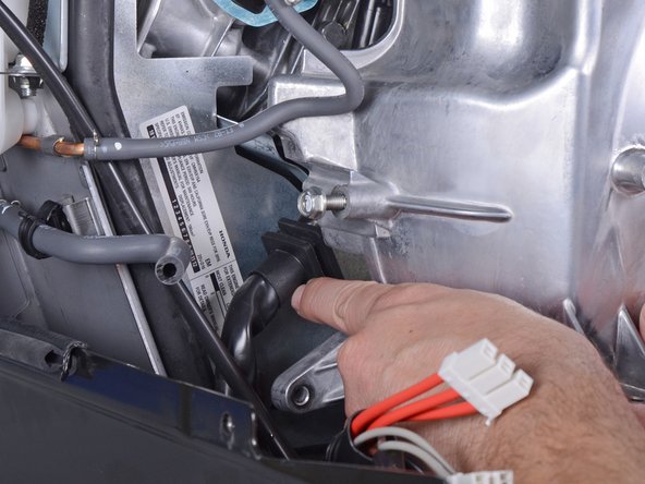
- Use a 12 mm socket to remove the mounting nuts securing the front bushings.
- Insert a pry bar underneath the fan cover.
- Pry upwards to lift the generator assembly slightly.
- As you lift the generator assembly with the pry bar, maneuver and remove the two generator mounts from their recess.
- Use a 10 mm socket to remove the long bolt from the fan cover.
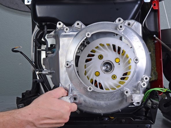
- Carefully pull the fan cover away from the generator assembly.
- During reassembly, make sure that the cord grommet is properly slotted into the fan cover.
- The fan cover is a tight fit. You may need to push the gas tank upwards as you maneuver the fan cover out.
- Remove the fan cover.
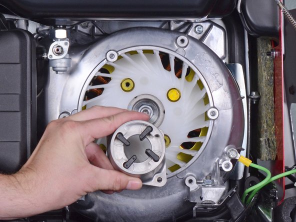
- Remove the cooling fan.
- Use a 19 mm socket to remove the nut securing the rotor to the generator shaft.
- During reassembly, tighten this nut to 55 ft-lb (74 N-m).
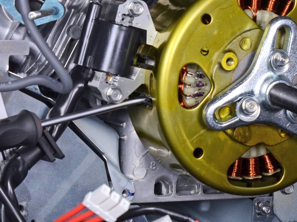
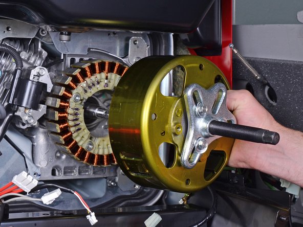
- Attach a flywheel puller to the rotor and use it to loosen the rotor.
- To prevent the rotor from spinning, insert a flathead screwdriver into one of the rotor slots and brace it against the ignition coil bracket.
- Be careful not to insert the screwdriver too deeply into the slot, or you will damage the stator.
- Remove the rotor.
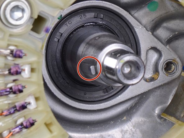
- Be careful not to lose the Woodruff key.
- During reassembly, be sure to align the rotor to the Woodruff key.
- After you install the replacement rotor, rotate it by hand to make sure that the rotor does not rub against the stator.
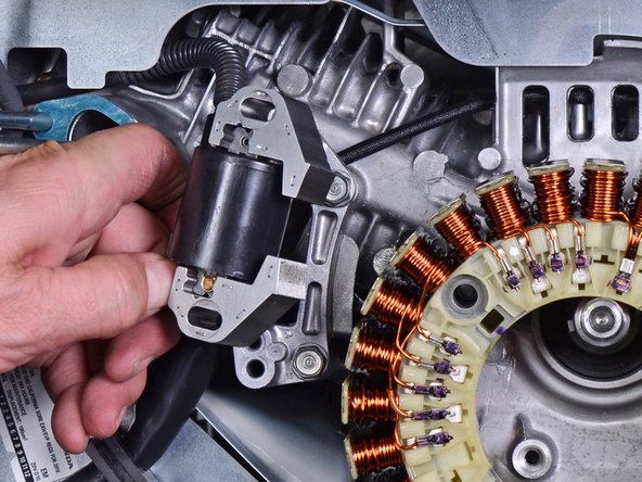
- Use a 10 mm socket to remove the two bolts securing the ignition coil.
- Loosen the ignition coil from the frame.
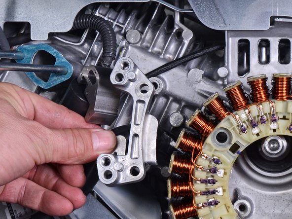
- Use a 10 mm socket to remove the two bolts securing the ignition coil bracket.
- Remove the ignition coil bracket.
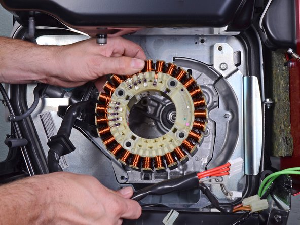
- Use a 4 mm hex key to remove the four bolts securing the stator.
- During reassembly, tighten these bolts to 8 lb-ft (11 N-m).
- Remove the stator.