Synology DS1019+ - a complete disassembly in rules
ID: 136272
Description: Here's a step-by-step tutorial to dismount...
Steps:
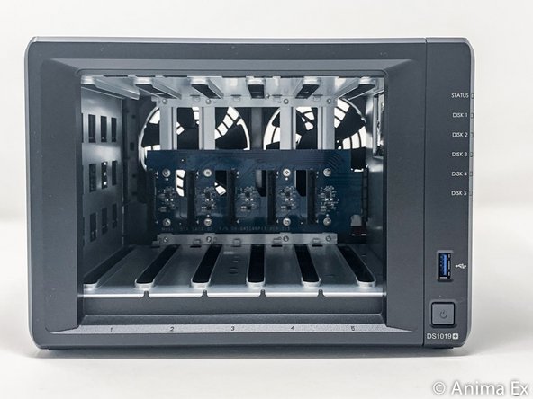
- Here are the different interesting faces of the case: front (bay disks), rear (connectors and fans), below (2 hatches SSD).
- This NAS DS1019+ is equipped with 8 GB of memory, an INTEL Celeron J3455 64-bit Quad processor, five bays for SATA drives.
- FRONT : disk cage lock / REAR : Kensington security incision (K-lock)
- 2 USB 3 ports (1 in front and 1 behind)
- 2 x RJ45 Gb ports.
- FRONT : 1 port for power supply
- BELOW : 2 M.2 NVMe 2280 ports (disk cache)
- REAR : 1 eSATA port
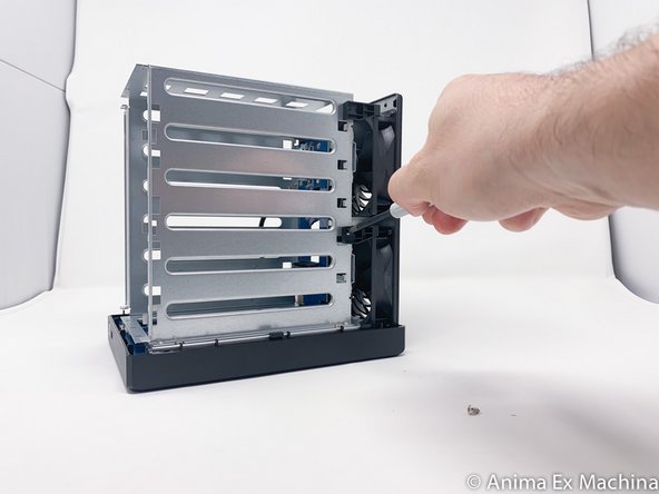
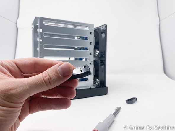
- Before teardown, unlock the disk media with the key.
- Since the media are unlocked, remove each disk media.
- This is a significant innovation, the memory is now directly accessible and without disassembly of the housing, for the original bar as for the extension port.
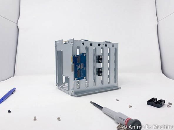
- backplane with 5 SATA connectors
- 2 memory slots
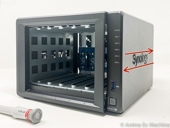
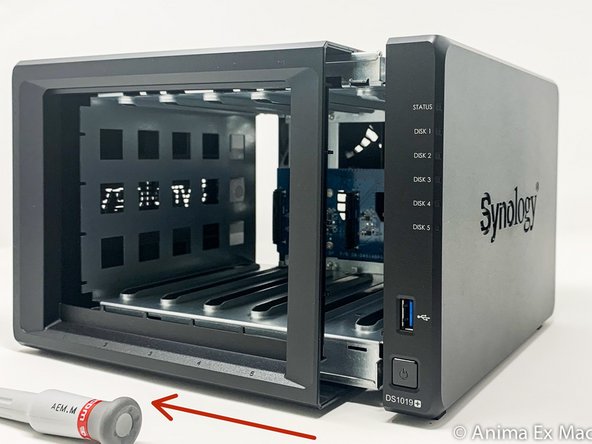
- Remove the 2 screws on the back of the case at the top and bottom (not the one above the USB port)
- Slide the cover forward, then slide it out (here, to the left).
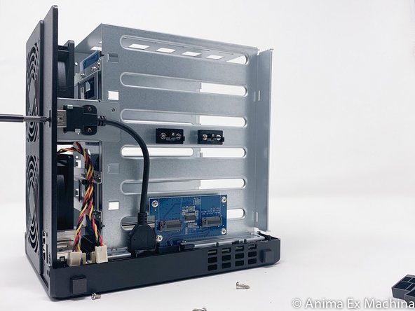
- in red: SSD M.2 expansion card 2280
- in yellow: USB 3 port
- in orange: internal connectors of the 2 fans
- in green: 2 slots of RAM
- in blue: SATA III backplane (5 hard drive bays)
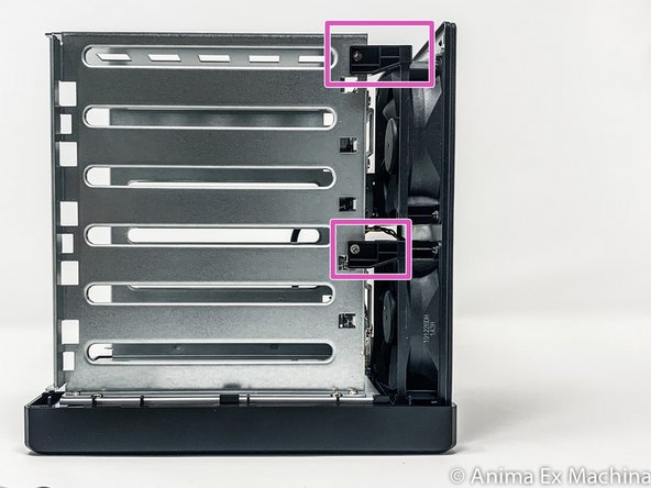
- in pink: fixing the fans on the chassis
- 3-PIN connectors of the fans
- Insérez ici votre traduction
- Insérez ici votre traduction
- Remove the 2 screws from the holding plate of the USB connector 3 and on the rear side.
- Then remove the USB3 metal plate.
- Removal of the SSD M2 board is not necessary for motherboard disassembly.
- Do not remove the USB connector 3 on the motherboard, it is glued. It does not interfere with disassembly!
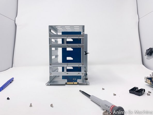
- Remove the screws from the two shims to secure the disc cage and the two fans.
- These plastic spacers are keyed
- 4 Phillips screws must be removed from two side.
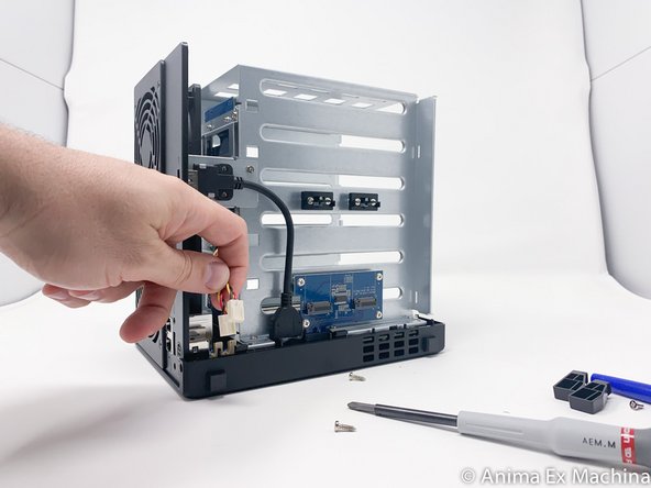
- Remove the fans's 3-PIN power cable
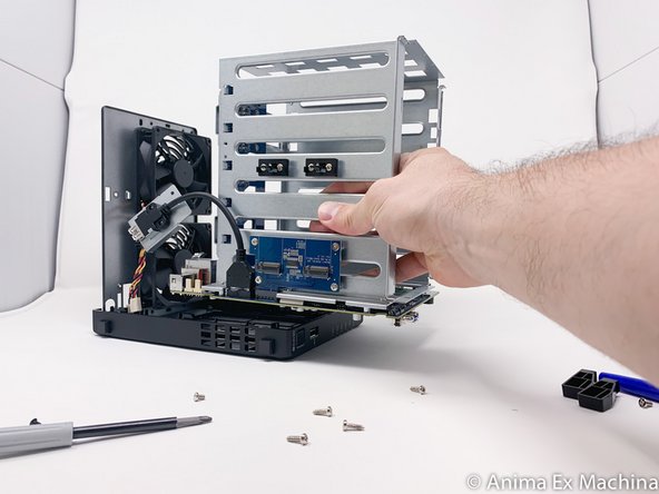
- Here, the motherboard is still secure to the disk cage.
- Remove the motherboard from the case paying attention to the USB 3 connector on the front and the power button. To do this, move the front panel a little and lift the motherboard upwards (outside).
- Take care.
- Once the motherboard is out, unscrew the 4 screws of the metal protective cover (metal plate).
- Motherboard processor side
- INTEL Celeron J3455 / 64-bit / Quad core 1.5 burst up to 2.3 GHz
- Memory battery
- Internal beep
- USB 3 port
- Power button
- Flash memory
- Memory side of the motherboard (pre-equipped with 8 GB of RAM)
- NVMe M.2 SSD expansion card connector
- Connector (PCIe ??) for SATA disk expansion card
- Fan connector (x2)
- Power connector
- RJ45 LAN Connector x2
- eSATA connector
- 2 x 4GB DDR3L 1866 RAM Memory Stick