Xiaomi Mi 10 Motherboard Cover & Charging Coil Removal
ID: 136407
Description: Prerequisite only! Use this guide to remove the...
Steps:
- Before you begin, switch off your phone.
- Apply a heated iOpener to the back of the phone to loosen the adhesive beneath the back cover. Apply the iOpener for at least two minutes.
- Secure a suction handle to the bottom of the rear glass, as close to the edge as possible.
- If the phone's rear glass is cracked, the suction handle may not stick. Try lifting it with strong tape, or superglue the suction handle in place and allow it to cure so you can proceed.
- Lift the rear glass with the suction handle to create a small gap between the glass and the frame.
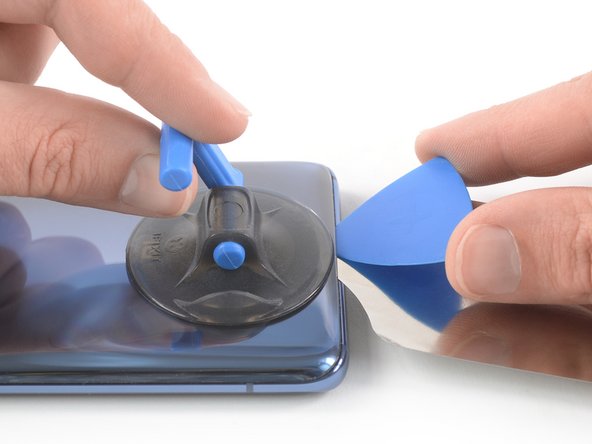
- The rear glass of the Xiaomi Mi 10 sits tightly in place. In order to create a gap that is big enough to insert an opening pick, you need to insert an iFlex first.
- Insert the iFlex into the gap and leave it in place to prevent the adhesive from resealing.
- Insert an opening pick into the gap you created with the iFlex.
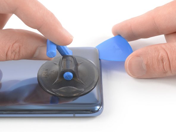
- Slide the opening pick to the bottom right corner.
- At this point you can remove the iFlex from the phone.
- Insert a second opening pick and slide it to the bottom left corner to cut the adhesive.
- Leave the opening picks in place to prevent the adhesive from resealing.
- Insert a third opening pick at the bottom left corner.
- Slide the tip of the opening pick from the bottom left corner along the side of the phone to cut the adhesive.
- Leave the opening pick in its place at the top left corner to prevent the adhesive from resealing.
- If the adhesive becomes hard to cut, it has most likely cooled down. Use your iOpener to reheat it.
- Insert a fourth opening pick under the top left corner of the rear glass.
- Slide the opening pick along the top edge of the phone to cut the adhesive.
- Leave the opening pick in the top right corner to prevent the adhesive from resealing.
- Insert a fifth opening pick at the top right corner of the phone.
- Slide the opening pick along the right side to cut the remaining adhesive.
- Remove the rear glass.
- During reassembly, this is a good point to power on your phone and test all functions before sealing it up. Be sure to power your phone back down completely before you continue working.
- Remove the four 4.9 mm Phillips #00 screws.
- Use an opening pick to slice the adhesive underneath the black protective mat covering the upper loudspeaker assembly.
- Use an opening pick to slice the adhesive underneath the black protective mat covering the bottom loudspeaker assembly.
- There is a small piece of protective copper foil underneath the NFC and charging coil assembly. Avoid damaging it during the following procedure.
- Slide a plastic card or playing card underneath the NFC and charging coil assembly.
- Use the card to carefully loosen the adhesive underneath the left edge of the assembly.
- To make this process easier, you can apply a heated iOpener to the left edge of the NFC and charging coil assembly to soften the adhesive.
- Do not remove the NFC and charging coil assembly all the way yet. It is still glued to the motherboard cover.
- Carefully fold the NFC & charging coil assembly to the left side of the phone.
- Remove the five 4.9 mm Phillips #00 screws.
- Slide an opening pick underneath the bottom right edge of the motherboard cover.
- Use the opening pick to pry up the motherboard cover.
- Remove the motherboard cover including the NFC and charging coil assembly.