Razer Kishi Direction Pad Replacement
ID: 140265
Description: Use this guide to replace the direction pad on...
Steps:
- The opening process is the same on both sides. For simplicity, this guide shows only the right-side opening process. Unscrew whichever side you wish to open and work on.
- For the right side, remove the five Y0 screws securing the right side of the controller.
- Four 9.2 mm screws
- One 7.2 mm screw
- If you wish to open the left side, remove the five Y0 screws securing the left side of the controller.
- Four 9.2 mm screws
- One 7.2 mm screw
- Both cases are held together by plastic clips.
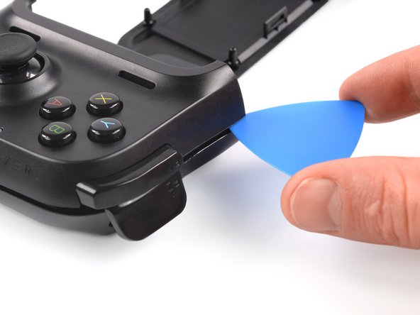
- Insert an opening pick in the seam between the top and bottom case, at the bottom left corner of the controller.
- With the pick still in the seam, slide it along the bottom edge to the bottom right corner to loosen the plastic clips.
- Slide the opening pick along the right edge to loosen the plastic clips.
- Slide the opening pick along the top edge to loosen the remaining plastic clips.
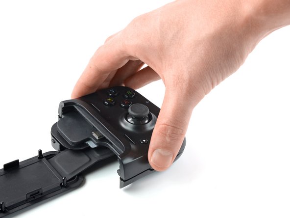
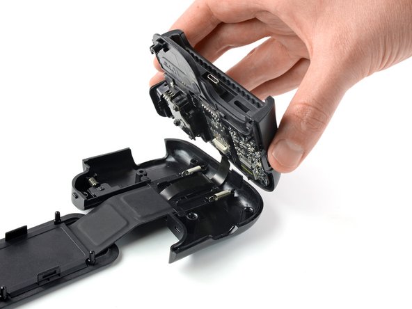
- Don't try to remove the top side yet, the case is still connected to the board.
- Carefully lift the top side and unfold it to the right, like a book.
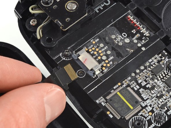
- Using the pointed end of a spudger, push the grey tabs on the interconnect socket away from the socket, parallel to the interconnect cable, to release the cable.
- Pull the cable out of the socket.
- Use a Phillips #0 screwdriver to remove the two 4.4 mm-long screws securing the trigger board.
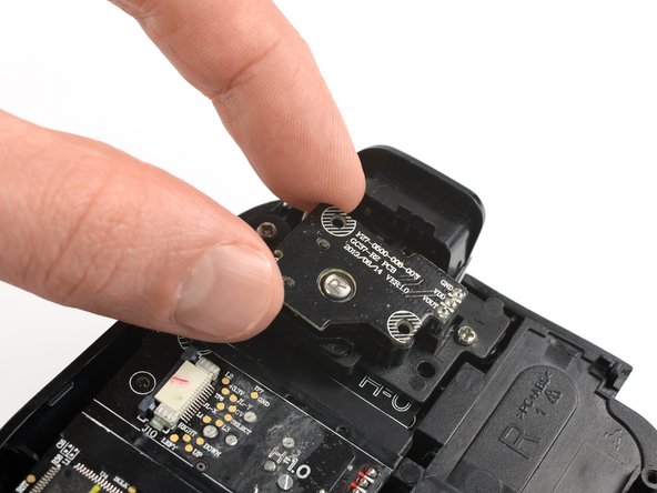
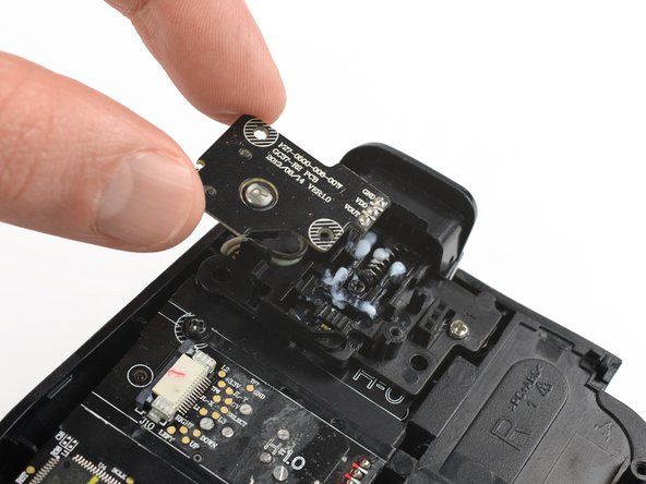
- The breakout board is plugged in. When removing breakout board, it is important to pull it straight out to avoid bending the connectors.
- Remove the breakout board by lifting it straight up, away from the controller.
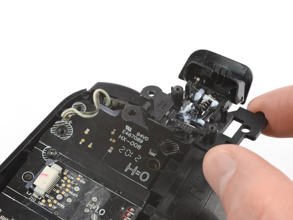
- Use a Phillips #0 screwdriver to remove the two 7.0 mm-long screws securing the trigger.
- Remove the shoulder trigger.
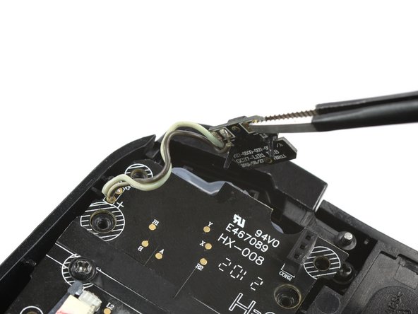
- Use a pair of blunt nose tweezers to lift out the shoulder button board.
- Use a Phillips #0 screwdriver to remove the two 5.9 mm-long screws.
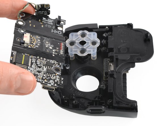
- Pull the mainboard straight out of the frame to remove it.
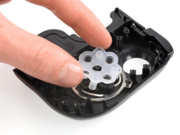
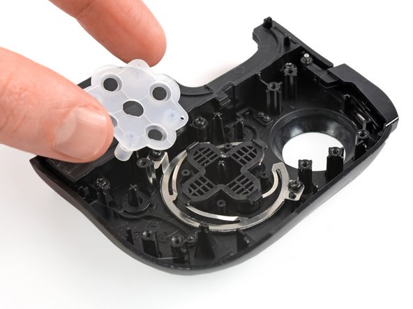
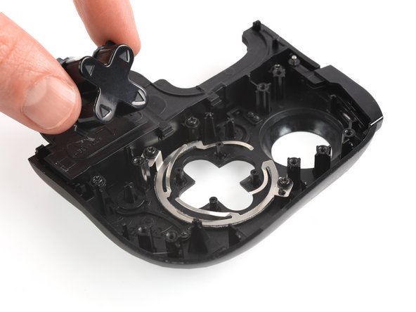
- Remove the rubber cover that is attached on top of the direction pad.
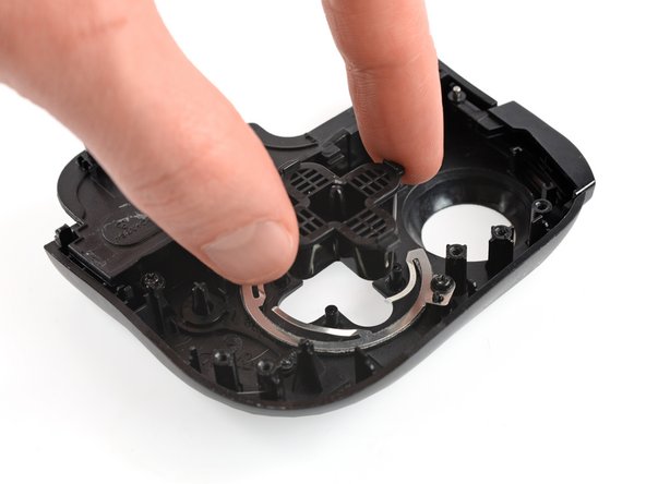
- Remove the direction pad.