Apple LED Cinema Display 27" LED Panel Replacement
ID: 140309
Description: Identifying Features The Apple LED Cinema...
Steps:
- Before beginning any work on your Mac: Unplug the computer and wait for 2 minutes in order for the power supply's capacitors to discharge.
- Be very careful not to touch the capacitor leads or any exposed solder joints on the back of the power supply.
- The all-in-one cable located underneath the power cable can NOT get disconnected from the rest of the enclosure.
- Glass panel can be removed in various ways:
- Lay the unit on its back and press clean suction cups in opposite corners on the glass panel, or...
- Lay the unit on its back and press clean suction cups on top.
- Lift the glass panel up and off.
- First Steps Remove the glass panel as shown on step 2.
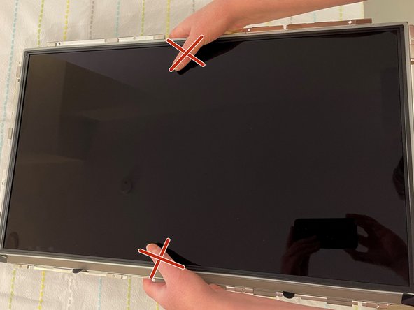
- Upon disassembly, handle the LED panel only from the metal railings on either side and avoid touching the panel as much as possible.
- Do not press on the front surface of the LED panel when handling, as this could cause the pixels from the panel to malfunction and/or stop working.
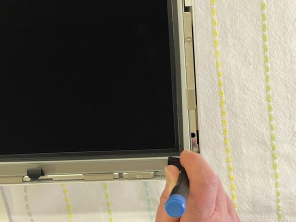
- Remove the twelve, 10 mm Torx T10 screws around the border of the display frame.
- Be sure not to overtighten the LED screws during reassembly, as it could cause light leakage after the unit is reassembled.
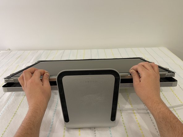
- Use the black tabs to raise the bottom edge of the LCD a few inches to access the cables inside.
- Tilt the display up no more than 4 inches (10 cm). Pulling the display too far could damage the cables or connectors.
- Avoid coming in close contact or touching any components of the Power Supply.
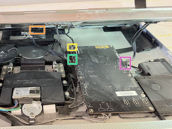
- Looking into the gap under the LCD, disconnect four (4) cables:
- DisplayPort
- Function
- Ground pin
- LED backlight driver
- Verify that all cables are firmly seated into connectors during reassembly. An insecure cable connection can cause image flicker.
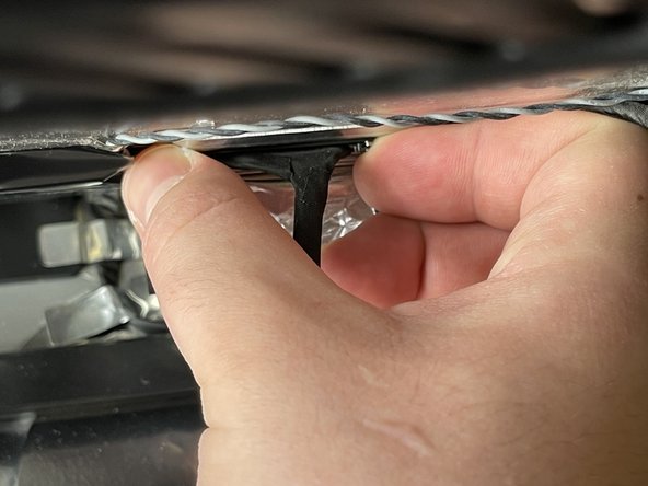
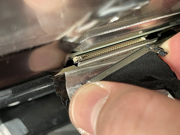
- Peel back the mylar and foil tape on the DisplayPort cable on the back of the LED panel.
- Squeeze the sides of connector and pull it out.
- Make sure the 24 pin cable is correctly aligned with the LED panel upon reassembly.
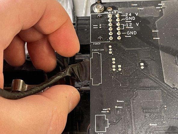
- Squeeze the sides of the function cable connector on the top left edge of the logic board and pull it straight out.
- Make sure to align the function cable correctly with the logic board during reassembly.
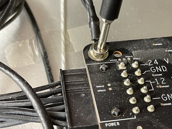
- Close-up of the ground cable at top left of logic board. Remove the 10 mm Torx T10 screw from top left corner of logic board.
- Disconnect the ground cable.
- Avoid touching the double pins on the top left corner of the logic board with a screwdriver.
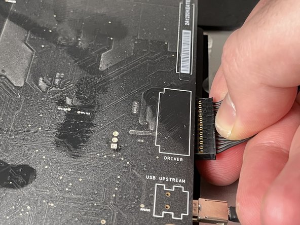
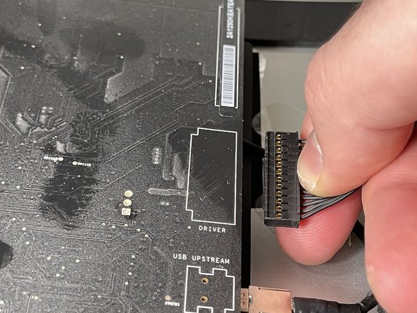
- Pinch the LED backlight driver cable on the underside of the center right edge of the logic board and pull straight out.
- Avoid putting force on the logic board to bend as deformation of a logic board can cause issues.
- Handle the LCD panel by the edges and lift it upwards until it separates from the rest of the enclosure.
- This guide can be followed in reserve in order to perform an installation and reassembly of the LED panel to the rest of the enclosure.