Samsung Galaxy Note20 Rear Camera Module Replacement
ID: 142072
Description: Use this guide to replace the rear camera...
Steps:
- Insert a SIM eject tool, bit, or straightened paper clip into the SIM card tray hole on the top edge of the phone.
- Press the SIM eject tool into the SIM card tray hole to eject the SIM card tray.
- Remove the SIM card tray.
- If you accidentally inserted the SIM eject tool into a microphone hole, don't worry! You most likely didn't damage the microphone.
- Completely power off your phone before you begin disassembly.
- Heat an iOpener and apply it to the left side of the rear cover for one minute.
- A hair dryer, heat gun, or hot plate may also be used, but be careful not to overheat the phone—the screen, internal battery, and the plastic rear cover are susceptible to heat damage.
- Apply a suction cup to the heated edge of the rear cover, as close to the edge as possible.
- Pull up on the suction cup with strong, steady force to create a gap between the rear cover and the frame.
- Depending on the age of your phone, this may be difficult. If you are having trouble, apply more heat to the edge and try again.
- Insert an opening pick into the gap.
- Don't insert the opening pick more than 5 mm into the phone or you risk damaging the internal components.
- As you cut through the adhesive around the perimeter of the phone, don't insert the pick more than 5 mm to avoid damaging internal components.
- Slide the opening pick along the left edge towards the bottom left corner to cut through the adhesive.
- Leave the pick inserted in the bottom left corner to prevent the adhesive from re-sealing.
- Repeat the process of heating and cutting the adhesive along the three remaining sides of the rear cover.
- You can insert each new opening pick in the gaps created by the opening picks left in each corner.
- As you proceed, leave an opening pick in each corner to prevent the adhesive from re-sealing.
- If the rear cover is still attached to the frame after cutting through all four sides, try slicing through the adhesive again with an opening pick.
- Lift the rear cover straight up to remove it.
- Use a Phillips screwdriver to remove the six 4.0 mm screws securing the motherboard shield.
- If these screws have not been removed before, they may be difficult to remove as they have threadlocker on their threads.
- Throughout this repair, keep track of each screw and make sure it goes back exactly where it came from.
- Use a pair of tweezers to lift up and flip back the motherboard shield.
- Be careful when handling the motherboard shield because its edges are thin and sharp.
- While using a pair of tweezers to hold the motherboard shield out of the way, use the pointed end of a spudger to pry up the battery press connector.
- Take care to pry only under the edge of the connector to prevent damaging the socket itself and surrounding components.
- To re-attach press connectors like this one, carefully align and press down on one side until it clicks into place, then repeat on the other side. Do not press down on the middle. If the connector is misaligned, the pins can bend, causing permanent damage.
- While using a pair of tweezers to hold the motherboard shield out of the way, use the pointed end of a spudger to pry up the wireless charging coil press connector.
- Grip the motherboard shield with your fingers.
- Peel the wireless charging coil up and away from the device.
- The wireless charging coil is secured to the device with light adhesive.
- Remove the wireless charging coil.
- Use a Phillips screwdriver to unscrew the five 4.0 mm screws securing the loudspeaker to the frame.
- Insert the pointed end of a spudger underneath the loudspeaker near its top left screw hole.
- Use the spudger to pry up and detach the loudspeaker from the frame.
- Use a pair of tweezers to lift and remove the loudspeaker.
- Take care not to puncture or bend the battery with your tweezers—a punctured or bent battery may leak dangerous chemicals or cause a thermal event.
- Use a Phillips screwdriver to remove the five 4.0 mm screws securing the earpiece speaker to the frame.
- Insert the flat end of a spudger underneath the bottom edge of the earpiece speaker.
- Pry up the earpiece speaker to loosen it from the frame.
- The earpiece speaker clips to the frame along the top edge.
- Lift and remove the earpiece speaker.
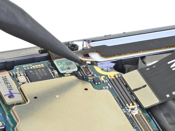
- Use the pointed end of a spudger to pry up the front-facing camera press connector.
- Because the front-facing camera is only attached to the motherboard by the press connector, it may fling out when you pry up the connector.
- Use a pair of tweezers to remove the front-facing camera.
- Use the pointed end of a spudger to disconnect the secondary interconnect cable from the daughterboard.
- Use the pointed end of a spudger to disconnect the main interconnect cable from the daughterboard.
- Use the pointed end of a spudger to disconnect the display cable from the motherboard.
- Use the pointed end of a spudger to disconnect the main interconnect cable from the motherboard.
- Use the pointed end of a spudger to disconnect the secondary interconnect cable from the motherboard.
- Use the pointed end of a spudger to disconnect the S-Pen press connector from the motherboard.
- Use the pointed end of a spudger to disconnect the green press connector from the motherboard.
- Use the pointed end of a spudger to disconnect the touch layer press connector from the motherboard.
- Use a Phillips screwdriver to remove the 4.0 mm screw securing the motherboard to the frame.
- Insert the pointed end of a spudger under the bottom left corner of the motherboard.
- Pry straight up to loosen the motherboard from the frame.
- Lift the motherboard out of the phone.
- Turn the motherboard over so that the rear camera module's press connectors are facing upward.
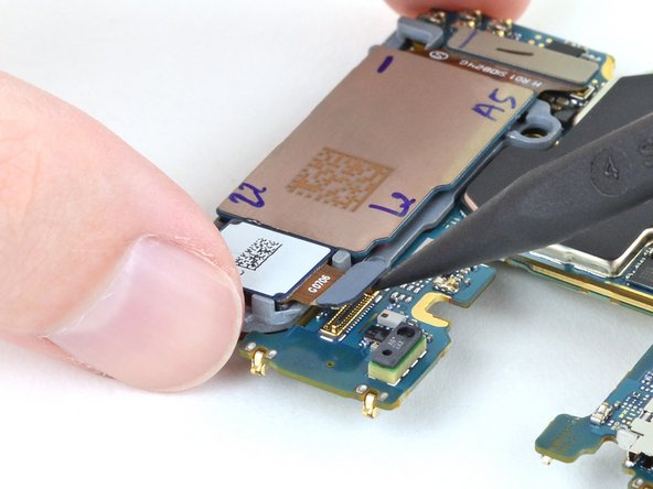
- Use the pointed end of a spudger to pry up the upper camera's press connector from the motherboard.
- Use a pair of tweezers to lift and remove the upper camera from the motherboard.
- Use the pointed end of a spudger to pry up the lower cameras' press connector from the motherboard.
- Lift and remove the lower cameras from the motherboard.