MacBook Air 13" Late 2020 Logic Board Replacement
ID: 142562
Description: Use this guide to replace the logic board in a...
Steps:
- Before starting this procedure, you should disable your Mac's Auto Boot feature. Auto Boot powers on your Mac when you open the lid, and may be accidentally triggered during disassembly. Use this guide to disable Auto Boot.
- If your MacBook is running Big Sur v11.1 or later, disabling Auto Boot may not work. You can proceed normally, but make sure to disconnect the battery as soon as you're inside.
- Completely power off and unplug your MacBook before you start. Close the display and flip the entire laptop upside-down.
- Use a P5 driver to remove the following screws:
- Two 7.9 mm screws
- Two 7.3 mm screws
- Six 2.6 mm screws
- Throughout this repair, keep track of each screw and make sure it goes back exactly where it came from to avoid damaging your MacBook.
- Wedge your fingers between the display and the lower case and pull upward to pop off the lower case.
- Remove the lower case.
- To reinstall the lower case:
- Set it in place and press firmly to engage the two hidden clips underneath. You should feel and hear them snap into place.
- Use the flat end of a spudger to pry up and unlatch the metal locking arm on the battery connector.
- Make sure the metal arm is completely free of the locking tab before lifting the battery connector. The metal locking arm should easily unlatch.
- Lift straight up on the metal locking arm to pull the battery connector out of its socket on the logic board.
- During reassembly, press the battery connector straight down into its socket, making sure it sits flush within the socket.
- If necessary, push the rear, wire side of the connector into place first, then rock the front of the connector into place.
- Use a T3 Torx driver to remove the three 1.4 mm screws securing the audio board connector cover.
- If your T3 bit feels a bit too loose, you may need to use a T4.
- Remove the audio board connector cover.
- Use the flat end of a spudger to pry the audio board connector straight up to disconnect it from the board.
- Use a T3 Torx driver to remove the two 1.4 mm screws securing the USB-C connector cover.
- If your T3 bit feels a bit too loose, you may need to use a T4.
- Remove the USB-C connector cover.
- Use the flat end of a spudger to pry the USB-C cable connector up and out of its socket on the logic board.
- Use a T3 Torx driver to remove the 1.4 mm screw securing the antenna cable cover.
- Remove the antenna cable cover.
- Use a pair of tweezers to grip the antenna connector close to its base.
- Pull straight up to disconnect the cable.
- Repeat for the second antenna cable.
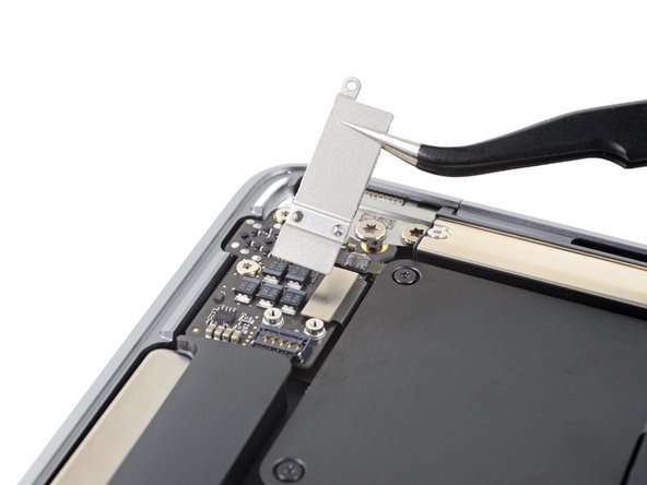
- Use a T3 Torx driver to remove the two 1.5 mm screws securing the display cable connector cover.
- Remove the display cable connector cover.
- Use the flat end of a spudger to pry the display cable connector straight off of the antenna board to disconnect it.
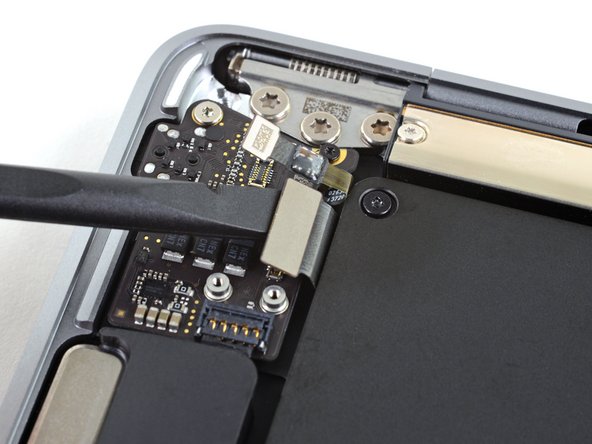
- Use a T3 Torx driver to remove the two 1.4 mm screws securing the trackpad cable cover.
- Remove the trackpad cable cover.
- Use the flat end of a spudger to pry the trackpad cable connector up and out of its socket.
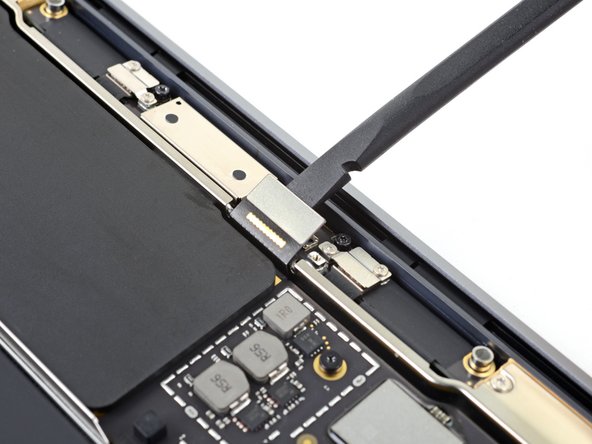
- The left speaker will be on your righthand side when working on the MacBook, as it's laying upside down.
- Slide the pointed end of a spudger underneath the left speaker cable and pry straight up to disconnect it from the logic board.
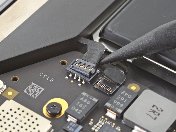
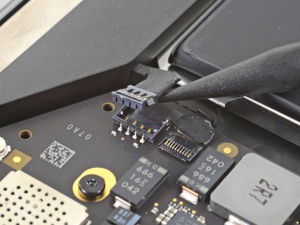
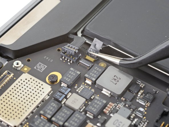
- Use a pair of tweezers to peel back any tape covering the microphone cable connector.
- Use the pointed end of a spudger to lift up the small locking flap on the microphone cable's ZIF connector.
- Slide the microphone cable out of its connector.
- If possible, grip the cable by the tape, not by the cable itself.
- Use a T5 Torx driver to remove the six screws securing the logic board to the upper case:
- Three 3.5 mm screws
- One 6.0 mm cushioned screw
- Two 3.4 mm screws
- Remove the logic board.
- When you reinstall the logic board assembly, verify that no cables get trapped under the board as you lower it into place. Check each of the seven locations carefully:
- Battery cable
- Audio board cable
- USB-C board cable
- Antenna bar cables
- Display cable
- Trackpad cable
- Left speaker and microphone cables