Sony Clie PEG-NR70 Motherboard Replacement
ID: 14443
Description: Installing a new motherboard involves removing...
Steps:
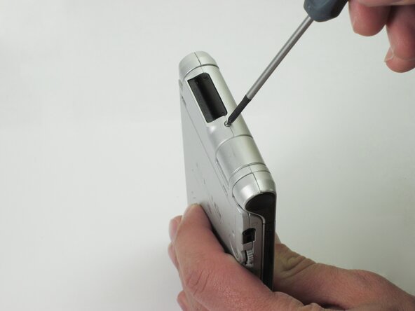
- Unscrew the 1.9mm screw located at the top of the device with a Phillips #00 screwdriver.
- It may be helpful to set up a piece of paper to keep track of where removed screws came from.
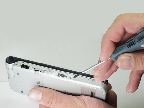
- Unscrew the 2.5mm screw located on the left side of the device with a Phillips #00 screwdriver.
- Unscrew the five 2.5mm screws on the back panel with a Phillips #00 screwdriver.
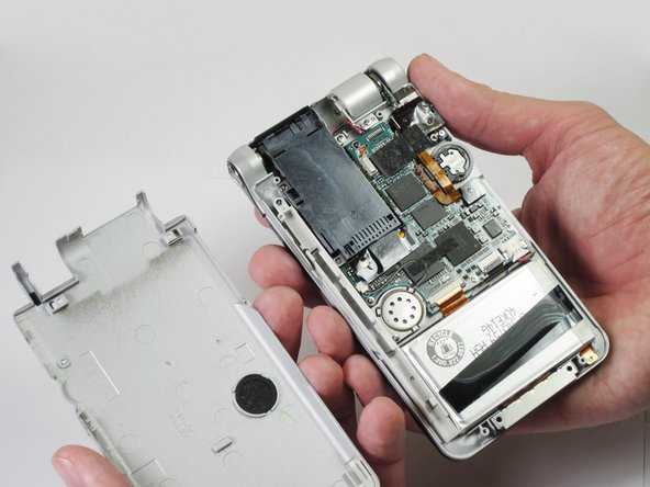
- Remove the back panel by lifting it away with your hands.
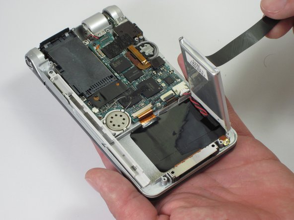
- Pull up on the black tab on the battery pack to reveal the power cord.
- Disconnect the battery pack from the motherboard by unplugging the power cables. Gently pull the wire toward the bottom of the device.
- Be careful to not tear the cables! They are very thin.
- Gently peel back the adhesive to completely disconnect the battery pack from device.
- Holding the memory module in place, unscrew the three 0.9mm screws with a Phillips #00 screwdriver.
- Lightly grab the memory module and pull it upwards.
- Make sure you grab the end closest to the edge of the device. You may have to wiggle the module a bit to get it to come free.
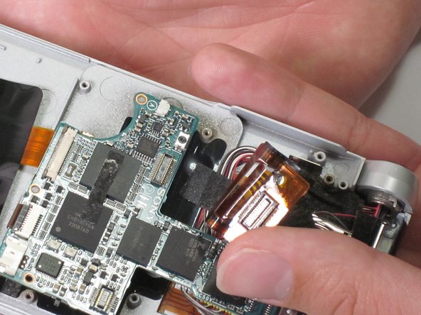
- Unscrew the 2.5mm screw on the top portion of the audio module with a Phillips #00 screwdriver.
- Remove the tape that is holding the module down.
- Lift up the orange ribbon cable and unscrew the two 2.5mm screws located at the corners of the audio module with a Phillips #00 screwdriver.
- Unplug the audio module from the motherboard by disconnecting the wires by lifting the orange wire up.
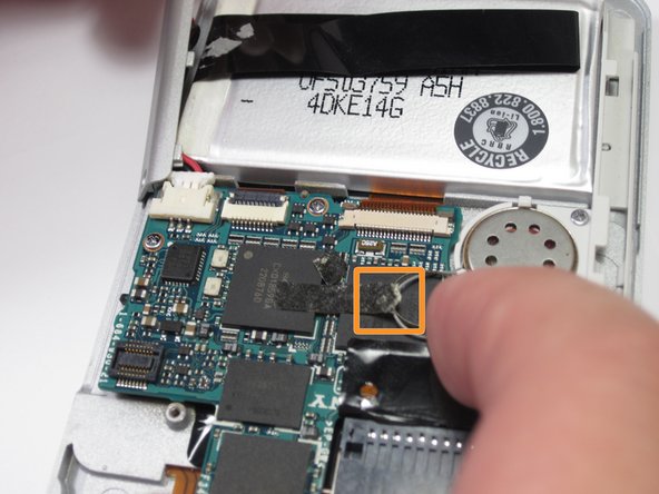
- Use tweezers to unplug the speaker wire from the motherboard by pulling the plug (not the wires) down towards the speaker.
- Be careful not to tear the speaker wires! They are very thin.
- Remove the tape holding speaker wire by peeling it away.
- Holding down the speaker rail unscrew the two 2.5mm screws with a Phillips #00 screwdriver.
- Remove the speaker rail vertically from the device.
- Unplug the ribbon cable found near the bottom of the motherboard by pulling it towards the bottom of the device.
- Be careful not to tear the plug! It is very thin.
- Unplug the ribbon cable connected at the bottom of the memory module by prying it up with a spudger.
- Unplug the wires found underneath the right side of the "stem" of the motherboard by pulling gently.
- Be careful not to tear the wires! They are very thin.
- Lift up the black locking tab holding the ribbon cable in place.
- Gently pull on the ribbon cable to remove it from the ZIF connector.
- Be careful not to tear the ribbon cable! It is very thin.
- Unplug the yellow connector from the underside of the left side of the motherboard by pulling gently.
- Be careful not to tear the wires! They are very thin.
- Unplug the second yellow connector from the underside of the right side of the motherboard by pulling gently.
- Be careful not to tear the wires! They are very thin.
- Unplug the last set of wires from underneath the top of the motherboard.
- Be careful not to tear the wires! They are very thin.
- The motherboard should be loose now. You should be able to wiggle it free from the housing.