Microsoft Surface Laptop 3 13.5" Motherboard Replacement
ID: 144778
Description: Use this guide to remove or replace the...
Steps:
- Flip the laptop over and place it on your work surface, feet facing up.
- The feet on the bottom of the laptop are meant to be removed with the pointed end of a spudger.
- Each foot has a hidden indent that will simplify removal.
- To make sure the spudger is in the indent, insert it at the nearest long edge, pushing parallel to the short edges of the laptop, as shown.
- Note that the two feet near the rear (screen) edge are different than the two front feet.
- Insert the pointed end of a spudger underneath one of the two rear feet, at its rear edge.
- Push the spudger underneath the foot and pry up to release it.
- The two rear feet are secured with some light adhesive.
- Repeat to remove the second rear foot.
- Insert the pointed end of a spudger underneath one of the two front feet, at its front edge.
- Push the spudger underneath the foot and pry up to release it.
- The two front feet are secured with plastic clips as well as light adhesive.
- Repeat to remove the second front foot.
- During reassembly:
- Note that the front and rear feet are different.
- Note that the front feet are directional and only clip in one way.
- In place of reusing old, worn out feet on your device, 8 mm rubber furniture pads can be a good substitute.
- Peel a pad away from its backing, align it over a foot cavity, and press to secure.
- Use a T5 Torx driver to remove the four 3 mm screws in the foot cavities securing the upper case to the device.
- Throughout this repair, keep track of each screw and make sure it goes back exactly where it came from to avoid damaging your laptop.
- During reassembly, don't over-tighten these screws—they strip easily.
- Flip the device over.
- Open the display as far as it will go.
- The upper case is secured in place by magnets.
- Grip the top edge of upper case above the keyboard and lift straight up to release it.
- Don't try to completely remove the upper case just yet, as it's still connected to the rest of the laptop.
- Lift the front edge of the upper case up and away from the laptop, taking care to not strain the keyboard and touchpad ribbon cable underneath.
- During reassembly, lower the upper case onto the lower case until the magnets snap into place and it lays flat.
- Check that the upper case sits flush around the entire perimeter. Any gaps between the upper and lower case near the display could cause damage to the display as it closes.
- The keyboard and touchpad ribbon cable is secured in place by a magnet connector.
- On some models, this connector is surrounded by black tape.
- Insert the flat end of a spudger underneath one edge of the ribbon cable connector, and pry up to release it.
- Remove the ribbon cable from the motherboard.
- Remove the upper case.
- Set the upper case onto a clean surface, keyboard-side down.
- Ensure the ribbon cable lays flat, and isn't twisted or stressed.
- Use a T5 Torx driver to remove the 2.7 mm screw securing the SSD.
- Removing the SSD also functions as a battery disconnect and should be performed before all major repairs.
- With the SSD screw removed, the SSD will pop up at a shallow angle.
- Grip the end of the SSD and pull it away from its board connector to remove it.
- During reassembly, insert the SSD at a shallow angle into its board connector, and secure it back into its horizontal position with the SSD screw.
- Use a pair of tweezers to remove the two pieces of black tape covering the bottom left and bottom right corners of the motherboard.
- During reassembly, reapply the tape if it's sticky enough to be reused.
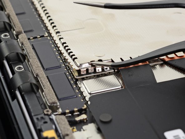
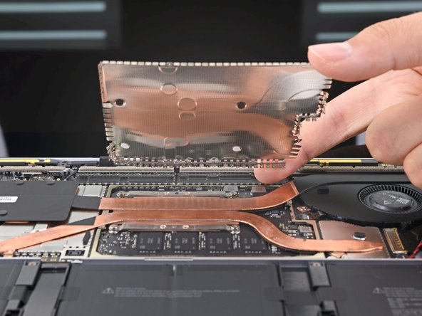
- Insert the tip of one arm of a sharp pair of tweezers into one of the holes near the top left corner of the heatsink shield.
- Pull upwards to release the top left corner of the shield.
- This may require a considerable amount of force, but try not to deform the shield too much—you'll need to reinstall it during reassembly.
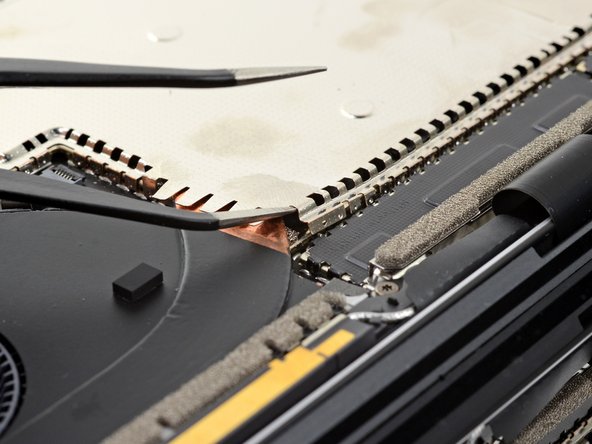
- Repeat the previous step's procedure to release the top right corner of the heatsink shield.
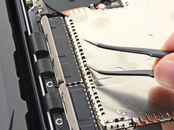
- Continue along the heatsink's top edge, inserting a tweezer arm into the shield holes and prying upwards on each one as you go.
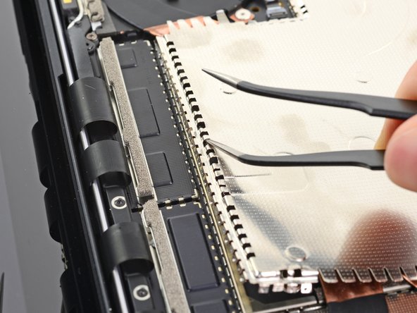
- Once the top edge is loose, use your fingers to grip the top of the shield and pull it up and away from the heatsink to release the remainder of the shield.
- Try not to deform the shield too much—you'll need to reinstall it during reassembly.
- Completely remove the heatsink shield.
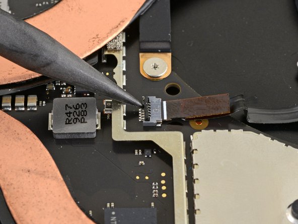
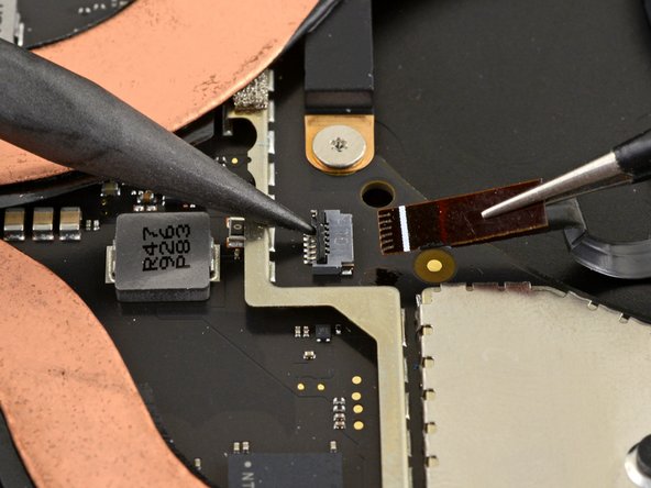
- Use the pointed end of a spudger to flip up the locking flap on the fan cable's ZIF connector.
- Use a pair of tweezers to pull the fan cable straight out of the connector.
- Use a T3 Torx driver to remove the nine screws securing the heatsink:
- One 2.5 mm screw
- Three 2.0 mm screws
- One 3.0 mm screw
- Two 4.1 mm screws
- Two 3.4 mm screws
- During reassembly:
- Align the heatsink with the centering peg on the motherboard.
- Tighten the four CPU tension screws in an "X" pattern.
- Use the tip of your finger to lift the far right edge of the heatsink up and off of the small alignment peg near the right side of the fan on the lower case.
- Once the heatsink has cleared the peg, lightly pull the right edge towards the front of the device.
- Remove the heatsink.
- If the heatsink feels stuck to the CPU, gently wiggle it side-to-side to separate it from the thermal paste holding it down.
- Don't pull on the heatsink too hard; the heat pipes are susceptible to creasing.
- Before reinstalling the heatsink, follow this guide to clean the heatsink and CPU and reapply thermal paste.
- Some motherboard screws are located under two of the metal shields, both of which need to be removed.
- Use an opening tool to pry up an edge of the metal shield covering the right side of the motherboard.
- Try not to deform the shield too much—you will need to reinstall it during reassembly.
- Work your way around the perimeter of the shield, prying up intermittently, until you can remove it completely.
- Remove the shield.
- Repeat the previous step to remove the second shield from the left side of the motherboard, closest to the CPU.
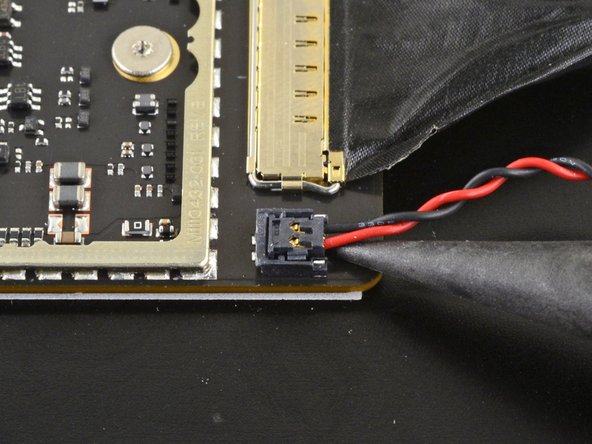
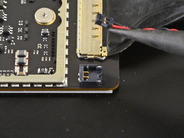
- Use the pointed end of a spudger to lift and disconnect the right speaker wire from its connector on the motherboard.
- Use an opening tool to flip open the gold locking arm on the Surface Connect port's motherboard connector.
- Grip the Surface Connect port cable and pull it away from its connector to remove it.
- Use the pointed end of a spudger to lift and disconnect the left speaker wire from its connector on the motherboard.
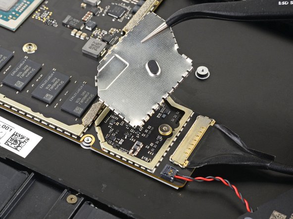
- Use an opening tool to pry up the black shield covering the right bank of display connectors.
- Try not to deform the shield too much—you will need to reinstall it during reassembly.
- Repeat at different points around the shield until it becomes loose.
- Remove the shield.
- Repeat the previous step to remove the remaining shield from the left bank of display connectors.
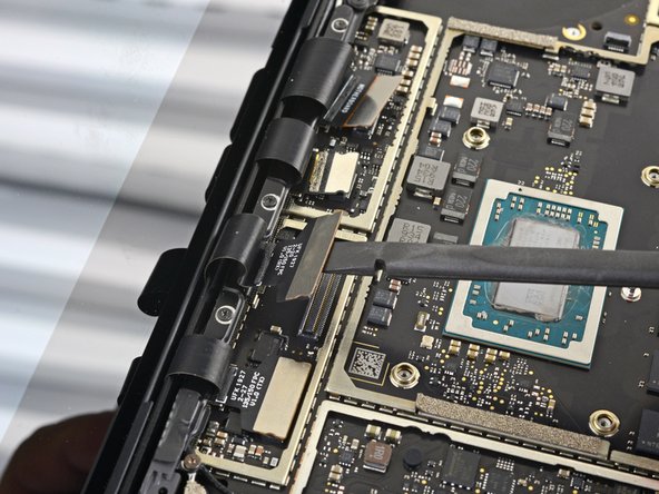
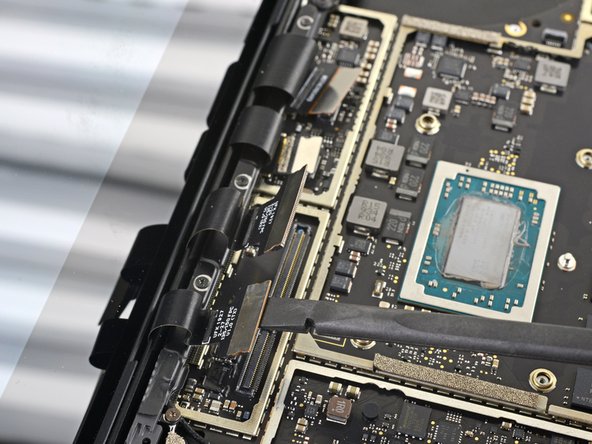
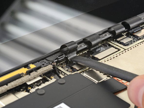
- Use the flat end of a spudger to pry the first display cable up and out of its socket on the motherboard to disconnect it.
- Disconnect the three remaining display connectors.
- During reassembly, use the flat end of a spudger to gently push the display cables back into their cavity in the lower case.
- Use a pair of tweezers to grip the antenna cable close to its base.
- Pull straight up to disconnect the cable.
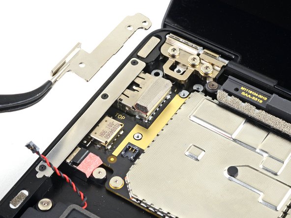
- Use a T3 Torx driver to remove the two 3 mm screws securing the motherboard bracket.
- Use a pair of tweezers to remove the motherboard bracket.
- Use a T3 Torx driver to remove the six 2 mm screws securing the motherboard.
- Optionally, to simplify motherboard removal, use a T3 Torx driver to remove the three screws securing the port bracket, then remove the bracket.
- Use your fingers to lift and remove the motherboard.
- If the motherboard feels stuck, slide the motherboard to the right so the I/O ports clear their cutouts on the chassis.
- Ensure the two screwpost braces underneath the motherboard don't get lost during removal.
- When you reinstall the motherboard, verify that no cables get trapped under the board as you lower it into place. Check each of the five locations carefully:
- Four display cables
- Antenna cable
- Left speaker cable
- Surface Connect cable
- Right speaker cable