iPad Pro 9.7" Logic Board Replacement
ID: 144822
Description: Follow this guide to remove or replace the...
Steps:
- Insert a SIM card eject tool, bit, or a paperclip into the small hole in the SIM card tray, located near the bottom edge of the iPad.
- Press firmly to eject the tray.
- Remove the SIM tray.
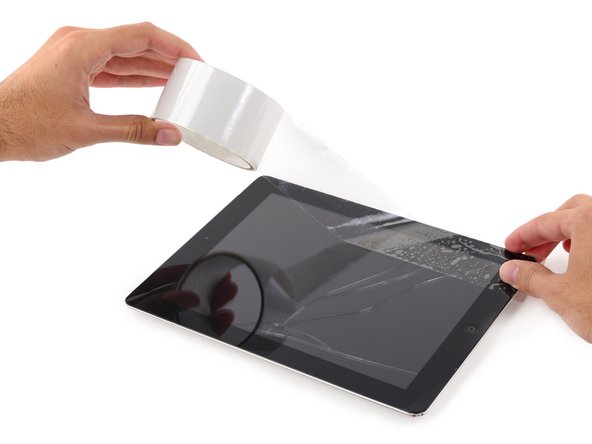
- If your display glass is cracked, keep further breakage contained and prevent bodily harm during your repair by taping the glass.
- Lay overlapping strips of clear packing tape over the iPad's display until the whole face is covered.
- This will keep glass shards contained and provide structural integrity when prying and lifting the display.
- Do your best to follow the rest of the guide as described. However, once the glass is broken, it will likely continue to crack as you work, and you may need to use a metal prying tool to scoop the glass out.
- Wear safety glasses to protect your eyes, and be careful not to damage the LCD screen.
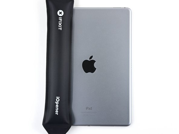
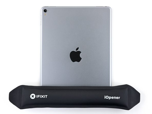
- The following steps involve using an iOpener to soften the adhesive holding the front panel assembly in place. When using the iOpener, be sure to heat it in the microwave for no more than 30 seconds.
- Handling it by the tabs on either end, place a heated iOpener over the top edge of the iPad.
- Let the iOpener sit on the iPad for two minutes to soften the adhesive securing the front panel to the rest of the iPad.
- While the iPad looks uniform from the outside, there are delicate components under certain portions of the front glass. To avoid damage, only heat and pry in the areas described in each step.
- As you follow the directions, take special care to avoid prying in the following areas:
- Home Button
- Front Facing Camera
- Main Camera
- The next two steps demonstrate the Anti-Clamp, a tool we designed to make the opening procedure easier. If you aren't using the Anti-Clamp, skip down two steps for an alternate method.
- For complete instructions on how to use the Anti-Clamp, check out this guide.
- Elevate the iPad enough for the Anti-Clamp's arms to rest above and below the screen.
- Pull the blue handle towards the hinge to disengage opening mode.
- Position the suction cups near the top edge of the iPad—one on the front, and one on the back.
- Push down on the cups to apply suction to the desired area.
- If you find that the surface of your device is too slippery for the Anti-Clamp to hold onto, you can use packing tape to create a grippier surface.
- Push the blue handle away from the hinge to engage opening mode.
- Turn the handle clockwise until you see the cups start to stretch.
- Make sure the suction cups remain aligned to each other. If they begin to slip out of alignment, loosen the suction cups slightly and realign the arms.
- Wait one minute to give the adhesive a chance to release and present an opening gap.
- Insert an opening pick under the screen when the Anti-Clamp creates a large enough gap.
- If the Anti-Clamp doesn't create a sufficient gap, apply more heat to the area and rotate the handle clockwise half a turn.
- Don't crank more than a half a turn at a time, and wait one minute between turns. Let the Anti-Clamp and time do the work for you.
- Skip the next two steps.
- Place a suction cup over the iPad's front-facing camera and press down to create a seal.
- To get the most leverage, place the suction cup as close to the edge as possible without going past the edge of the display.
- Firmly pull up on the suction cup to create a small gap between the front panel and the rear case.
- Do not pull too hard or you may shatter the glass.
- Once you've opened a sufficient gap, insert an opening pick into the gap to prevent the adhesive from resealing.
- Slide the pick along the edge of the display, towards the headphone jack.
- If there is still a considerable amount of resistance when sliding the opening pick, repeat the iOpener heating procedure and apply additional heat.
- Don't insert the pick past the bezel into the display area, or you will damage it.
- A good rule of thumb is to never insert the opening pick more than a quarter inch into the iPad.
- Insert a second opening pick by the front-facing camera.
- Slide the second pick along the top edge of the iPad, towards the Sleep/Wake Button.
- Insert a third pick by the front-facing camera.
- Bring the right opening pick down and around the top right corner of the iPad.
- Bring the left opening pick around the top left corner of the tablet.
- Reheat the iOpener and lay it over the right edge of the display to loosen the adhesive underneath.
- Slide the right opening pick roughly halfway down the display.
- Reheat the iOpener and apply heat to the left side of the iPad.
- Slide the left-hand opening pick about halfway down the edge of the display.
- Slide the opposite opening pick down to the bottom right corner of the iPad.
- If necessary, reheat the adhesive on the right edge to loosen the display assembly.
- Slide the left-hand opening pick down the edge of the display until you reach the corner.
- Use the iOpener to apply heat to the bottom edge of the iPad.
- Bring the right-hand opening pick around the bottom corner of the iPad.
- Repeat for the left-hand pick.
- Reheat and reapply the iOpener as needed.
- Remove the right-hand opening pick at the bottom of the iPad.
- Slide the left-hand opening pick along the bottom edge of the display, then remove it from the bottom right corner of the iPad.
- Be very careful to not insert the pick more than a quarter inch into the display to avoid damaging the Home Button and display cables underneath.
- Use picks to ensure most of the adhesive has been cut through on the top, left, and bottom sides.
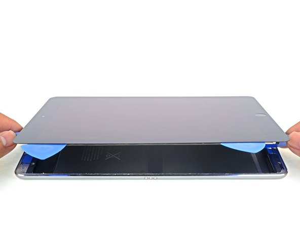
- Twist the top and bottom picks to separate the display assembly from the rear case.
- Do not attempt to remove the display—it is still attached to the rear case.
- Swing the display assembly towards the right of the case, using the right edge as a hinge.
- As you move the display assembly, make sure that the display ribbon cable is not being stressed.
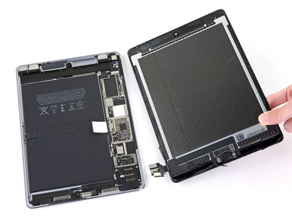
- Continue swinging the display assembly until it lays flat next to the rear case.
- Use a Phillips screwdriver to remove the eleven 1.3 mm screws securing the EMI shield.
- Apply a heated iOpener to the EMI shield on the logic board for one minute.
- Lift the logic board EMI shield, starting at the edge nearest the top of the iPad.
- Slowly peel the EMI shield up from the logic board.
- This takes a bit of force due to the many tiny clips securing the shield, and the shield may deform slightly. That's okay—try to keep the deformation to a minimum, and it will lay flat when reinstalled and screwed down.
- Remove the logic board EMI shield.
- Use a Phillips driver to remove the 1.7 mm-long screw securing the battery connector.
- If the EMI shield has any sharp protrusions after removal, you should flatten them before reinstalling the shield.
- Squeeze the sharp protrusion with a pair of pliers to flatten it.
- Repeat the process for all sharp protrusions along the edges of the EMI shield.
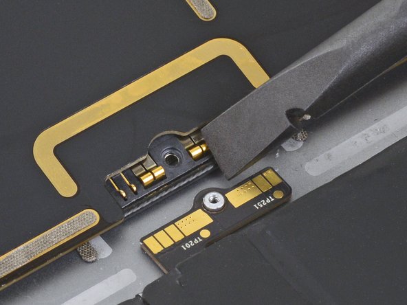
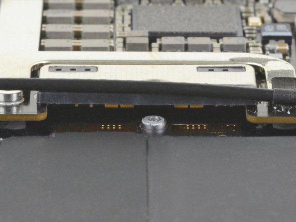
- These photos show what the battery connector looks like underneath the logic board. Use these photos as a reference while you safely disconnect the battery.
- Notice that the battery connector has cantilever springs on the logic board that press against the battery contact pads. Since both the logic board and battery are glued down, you'll need to slide something thin and flexible between the contact points to disconnect the battery.
- Be careful when you isolate the battery using a battery blocker. The battery contacts are easily bent or broken, resulting in irreversible damage.
- Ensure that the iFixit logo on the battery blocker is facing up.
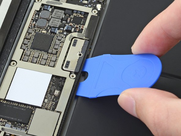
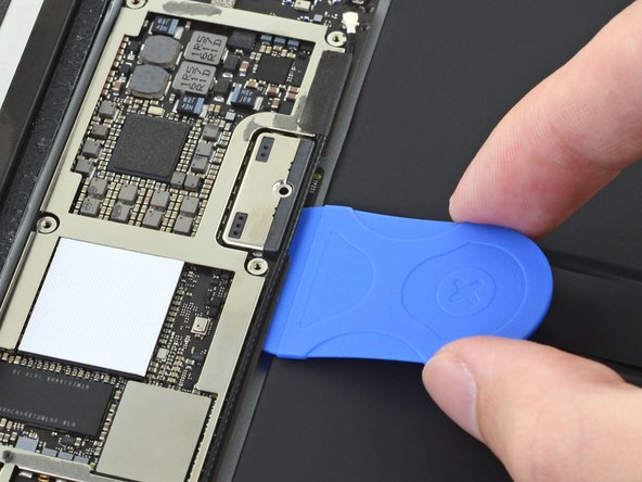
- Slide the battery blocker underneath the left side of the logic board's battery connector at a 35 degree angle.
- The battery blocker's right prong should slide between the left side of the logic board's battery connector and the battery's contact pads. The left prong should slide under the logic board.
- Don't push the battery blocker underneath the connector or logic board with excessive force. If you're having trouble fitting the battery blocker underneath the logic board, refer to the next step for information on loosening the logic board. You can also try using a playing card to disconnect the battery instead.
- The battery blocker or playing card should slide under the logic board without encountering any blockages. After insertion, they should rest at a 15 degree angle.
- Leave the battery blocker in place as you work.
- If the battery blocker doesn't easily slide under the logic board, follow these steps to partially loosen the logic board from the frame:
- Apply a few drops of high-concentration (90% or higher) isopropyl alcohol under the logic board to the left and right of the battery connection.
- Wait one minute for the isopropyl alcohol to weaken the adhesive under the logic board.
- Try to insert the battery blocker. If the logic board doesn't easily lift up, apply a few more drops of isopropyl alcohol.
- This doesn't apply when using the playing card method to disconnect the battery because the playing card is only inserted between the battery connector and the battery contact pads.
- Use a Phillips screwdriver to remove the three 1.3 mm Phillips screws securing the display cable bracket.
- Remove the display cable bracket.
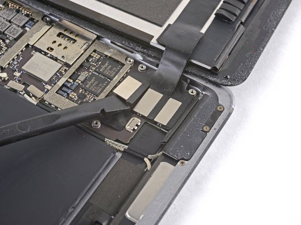
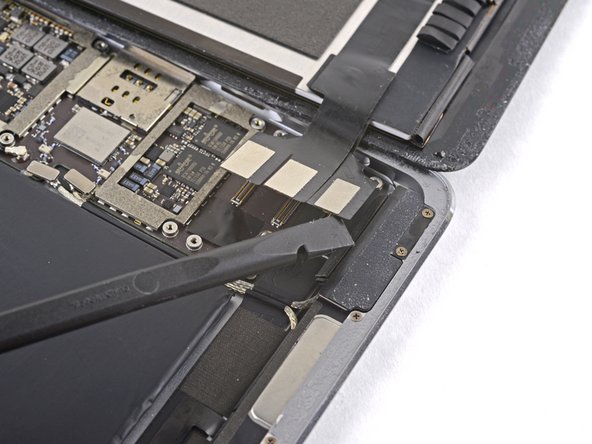
- Use the flat end of the spudger to disconnect the display assembly connector from the motherboard socket.
- Repeat the previous step for the two remaining connectors.
- Remove the display assembly from the frame.
- If you are reusing the original display assembly, follow this display adhesive application guide to apply replacement display adhesive during reassembly.
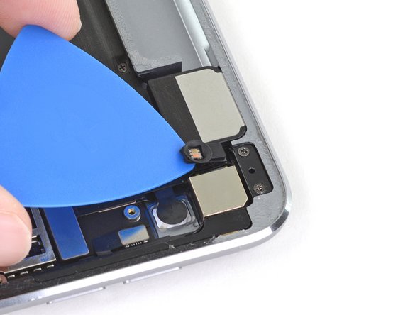
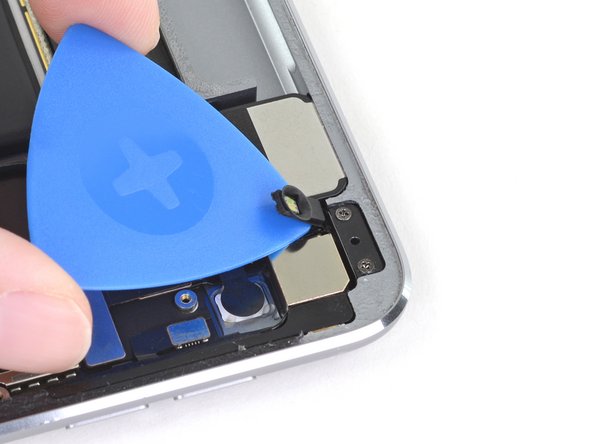
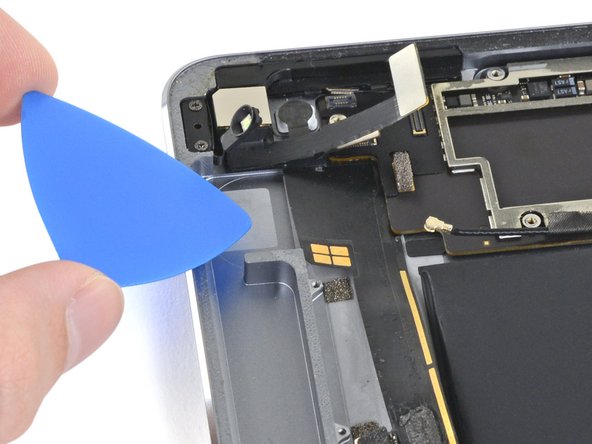
- Slide an opening pick under the right ambient light sensor to loosen its adhesive.
- There are two pegs on the shelf that position the ambient light sensor—one on the bottom edge and one near the top edge.
- Use a Phillips screwdriver to remove the four 1.9 mm-long screws securing the upper speaker to the frame.
- Strong adhesive secures the upper speaker to the frame.
- Apply a few drops of high-concentration (90% or higher) isopropyl alcohol under the upper speaker.
- Wait one minute for the isopropyl alcohol to weaken the adhesive under the upper speaker.
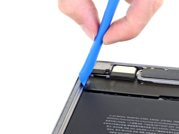
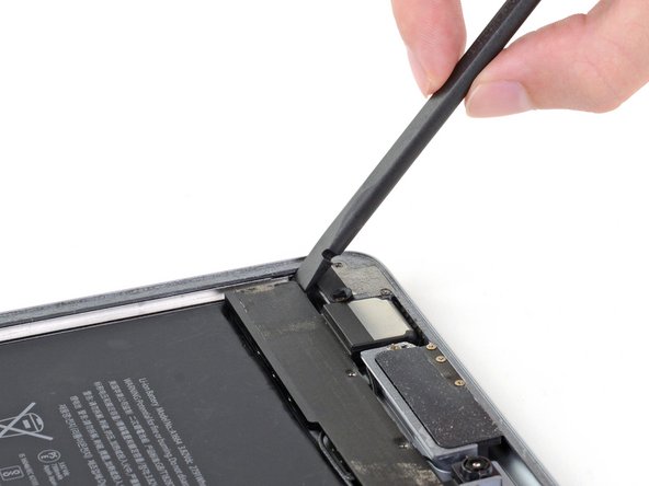
- Use an opening tool to pry up the left edge of the upper speaker.
- Try to avoid bending the upper speaker while prying it up. Some bending will likely happen during this process, but excessive bending may damage the upper speaker.
- If the upper speaker isn't detaching from the frame, apply a few more drops of isopropyl alcohol.
- Use the flat end of a spudger to push the left side of the upper speaker toward the battery just enough for the left speaker to slide out of its recess in the frame.
- Lift and remove the upper speaker from the frame.
- There are multiple cables under the upper speaker. Be careful not to damage them while removing it.
- If any cables are still attached to the upper speaker while you lift it up, carefully peel them off of the upper speaker. You can apply more isopropyl alcohol if they don't easily peel away.
- If the ZIF connector sticker near the front camera comes off while removing the upper speaker, reapply it to the ZIF connector.
- If the ZIF connector near the front camera disconnects while removing the upper speaker, use the pointed end of a spudger to flip up the locking flap. Then, reinsert the ribbon cable and close the locking flap.
- During reassembly, make sure the right ambient light sensor is on top of its shelf.
- If there's any alcohol solution remaining in the device, carefully wipe it off or allow it to air dry before reinstalling the upper speaker.
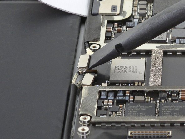
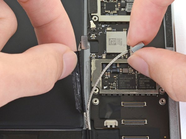
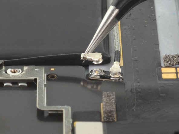
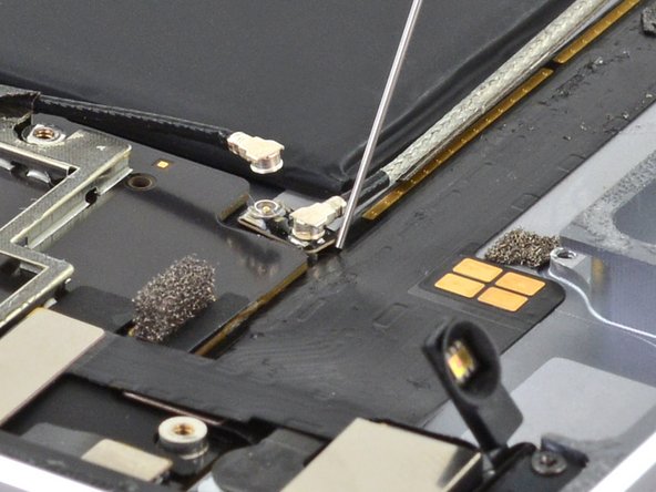
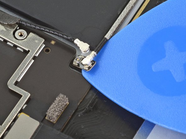
- Use the flat end of a spudger to disconnect the right antenna's coaxial connector from its socket.
- To reinstall, hold the connector in place and gently press straight down. The connector will “snap” into its socket.
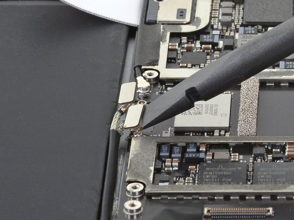
- Use the flat end of a spudger to disconnect the left antenna's coaxial connector from its socket.
- To reinstall, hold the connector in place and gently press straight down. The connector will “snap” into its socket.
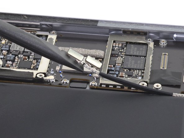
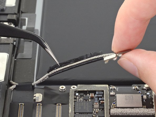
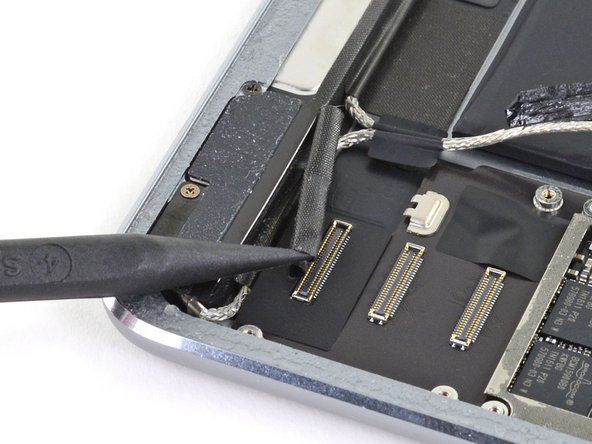
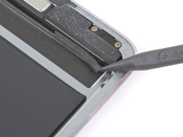
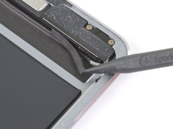
- Use the flat end of a spudger to lift the bundled left and right antenna cables away from the frame.
- Be careful not to puncture the battery with the spudger.
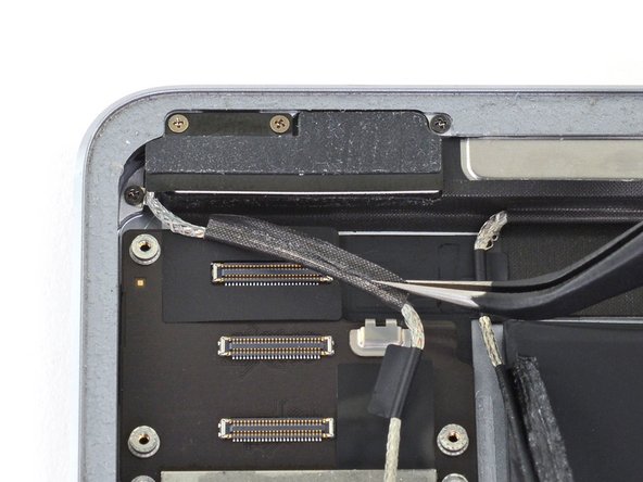
- The sticker bundling the antenna cables together is lightly adhered to the frame.
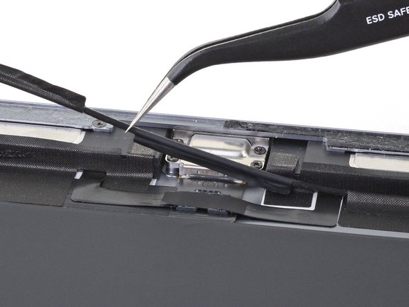
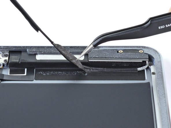
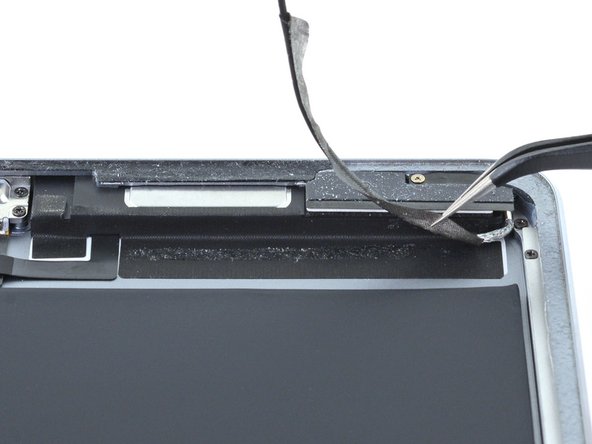
- Use a pair of tweezers to remove the adhesive that was securing the bundled antenna cables to the frame.
- Take care not to damage the antenna cables with the sharp tips on the tweezers.
- During reassembly, apply pre-cut adhesive to the bundled antenna cables to secure them to the frame.
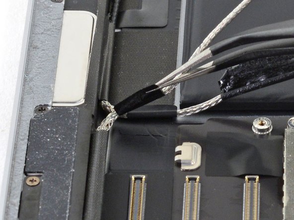
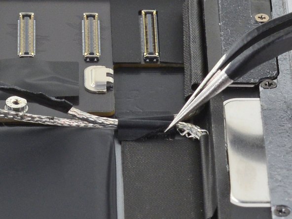
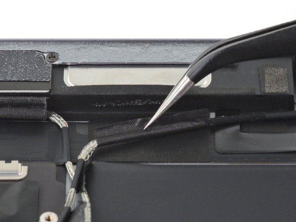
- Use a pair of tweezers to peel up the sticker bundling the left and right antenna cables together.
- Peel the right antenna cable off of the sticker.
- Use a pair of tweezers to lift up the small sticker near the lower right speaker securing the right antenna to the frame.
- Use the pointed end of a spudger to detach the foam spacer adhered to the second right antenna sticker.
- Remove the foam spacer from the second right antenna sticker.
- Use a pair of tweezers to detach the large right antenna sticker between the logic board and the antenna.
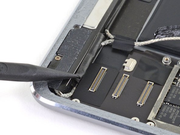
- Use a pair of tweezers to lift up the small sticker next to the lower right speaker securing the left antenna cable to the frame.
- Use a pair of tweezers to detach the large left antenna cable sticker near the lower right speaker.
- Use a pair of tweezers to lift the left antenna and its third sticker away from the Lightning port area of the frame.
- Use the pointed end of a spudger to detach the foam spacer adhered to the fourth left antenna cable sticker.
- Remove the foam spacer from the fourth left antenna cable sticker.
- Use a pair of tweezers to lift up the fourth left antenna cable sticker.
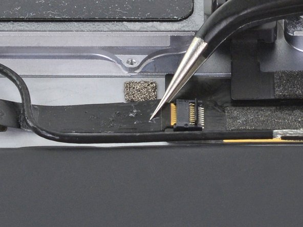
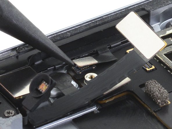
- Use a pair of tweezers to remove the sticker covering the left ambient light sensor's ZIF connector.
- Use the pointed end of a spudger to flip up the locking flap on the left ambient light sensor's ZIF connector.
- Use a pair of tweezers to grip the left ambient light sensor ribbon cable as close as possible to its contacts.
- Pull the ribbon cable out of the ZIF connector.
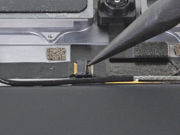
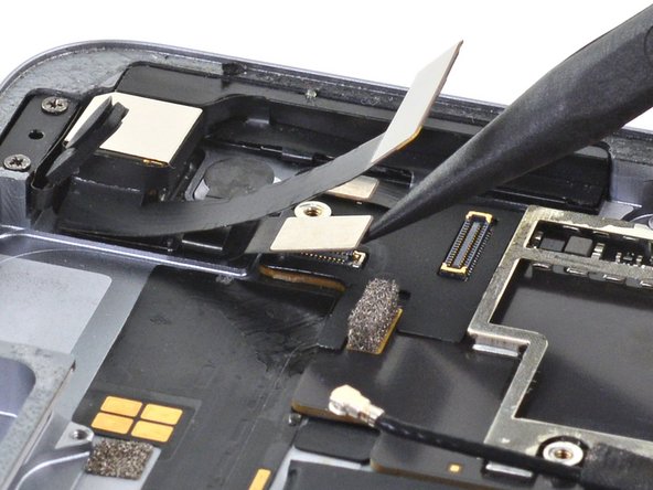
- Use the pointed end of a spudger to disconnect the front camera's press connector from its socket.
- Be careful to pry only under the edge of the connector, and not under the socket itself. If you pry under the socket, you will separate it from the circuit board.
- To reconnect, align the connector carefully over its socket and press down with your fingertip—first at one side, then the other—until it clicks into place.
- Do not press down on the middle until the connector is fully seated—if it's misaligned, the connector can bend, causing permanent damage.
- Use a pair of tweezers to grip the bottom coaxial connector on the top interconnect board by its metal frame.
- Lift straight up to disconnect the coaxial connector from the interconnect board.
- Apply a few drops of high-concentration (90% or higher) isopropyl alcohol to the edges of the top interconnect board.
- Wait thirty seconds for the isopropyl alcohol to weaken the adhesive under the top interconnect board.
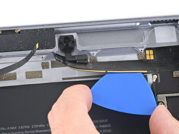
- Use an opening pick to cut through the adhesive under the top interconnect board and detach it from the frame.
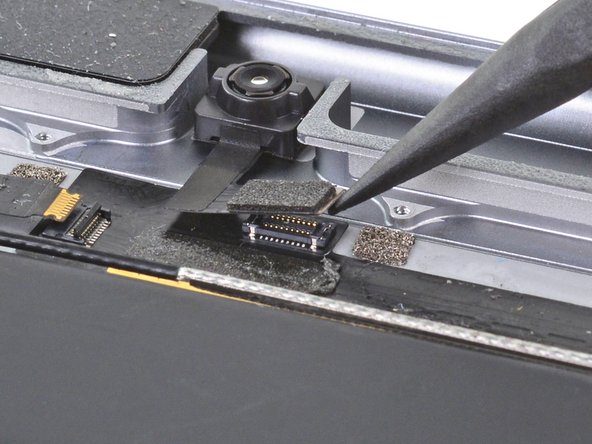
- Use the pointed end of a spudger to disconnect the rear camera's press connector from its socket.
- Use the pointed end of a spudger to disconnect the power button assembly's press connector from its socket.
- Use the pointed end of a spudger to disconnect the volume buttons' press connector from its socket.
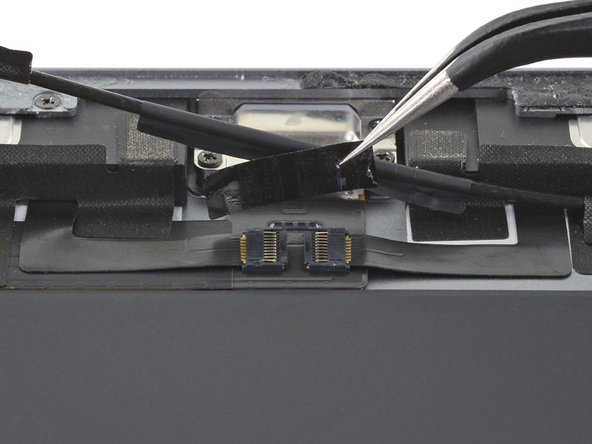
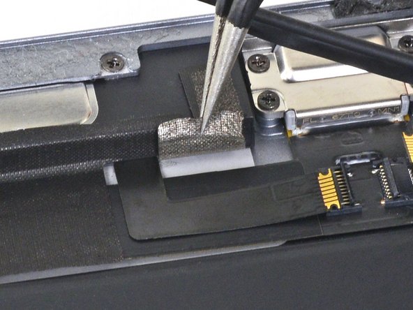
- Use a pair of tweezers to remove the sticker covering the ZIF connectors near the Lightning port.
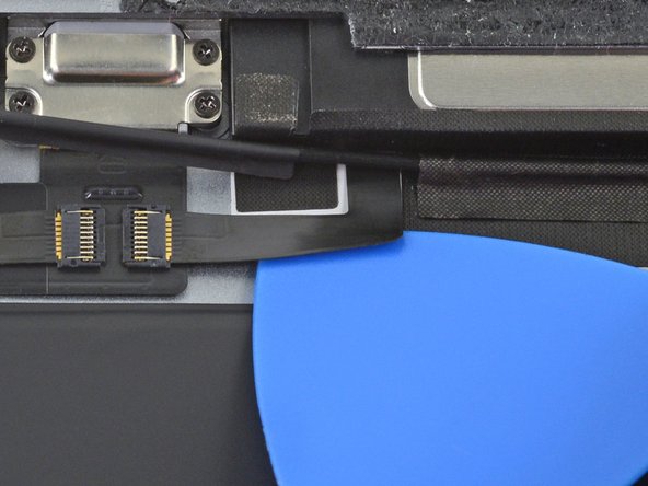
- Use an opening pick to cut through the adhesive under the right ribbon cable next to the lower speaker (Lightning port oriented up) and detach it from the frame.
- Be careful not to pull the ribbon cable out of the ZIF connector. Pulling the ribbon cable out while the ZIF connector locking flap is closed may damage the connection.
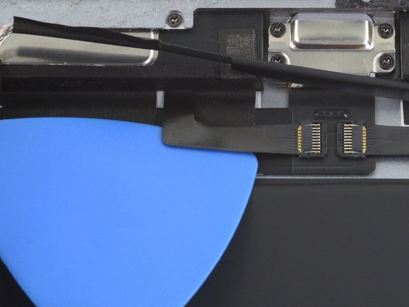
- Use an opening pick to cut through the adhesive under the left ribbon cable next to the lower speaker and detach it from the frame.
- Be careful not to pull the ribbon cable out of the ZIF connector. Pulling the ribbon cable out while the ZIF connector locking flap is closed may damage the connection.
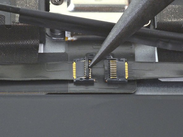
- Use the pointed end of a spudger to flip up the hinged locking flap on the left ribbon cable ZIF connector.
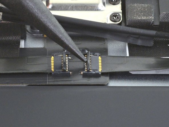
- Use the pointed end of a spudger to flip up the hinged locking flap on the right ribbon cable ZIF connector.
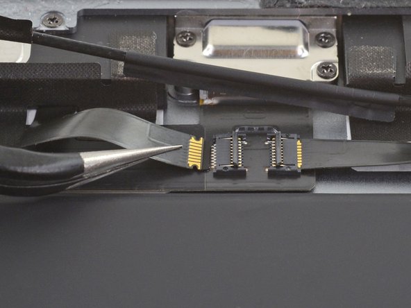
- Use a pair of tweezers to grip the left ribbon cable as close as possible to its contacts and pull the ribbon cable out of the ZIF connector.
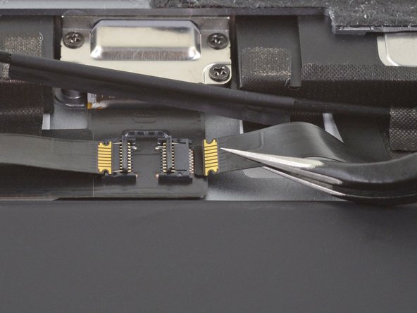
- Use a pair of tweezers to grip the right ribbon cable as close as possible to its contacts and pull the ribbon cable out of the ZIF connector.
- Remove the four Phillips screws securing the Lightning port:
- Two 2.5 mm screws
- Two 1.5 mm screws
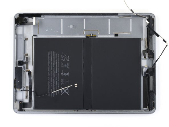
- This image shows the device with the logic board removed.
- Strips of adhesive secure the logic board to the frame. In the next steps, you'll weaken and cut through the adhesive to detach the logic board from the frame.
- Carefully turn the iPad over.
- Many cables are loose at this point. Make sure no cables are bent or torn while turning the iPad over.
- Heat an iOpener and apply it to the top, left, and bottom edges of the rear case for one minute on each edge.
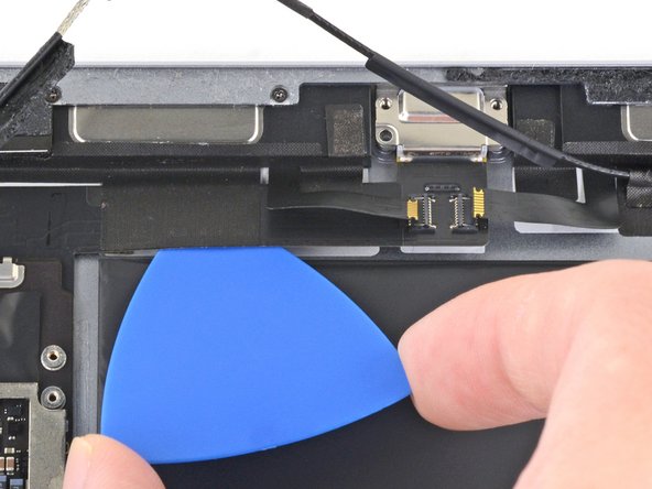
- Use an opening pick to cut through the adhesive under the Lightning port ribbon cable to detach it from the frame.
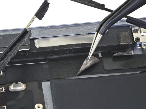
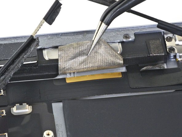
- Use a pair of tweezers to lift up the smaller sticker to the left of the Lightning port (when the Lightning port is oriented up).
- Use a pair of tweezers to lift up the larger sticker to the left of the Lightning port.
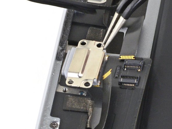
- Use a pair of tweezers to grip the Lightning port by the bottom right screw hole.
- Pull the Lightning port out of its recess.
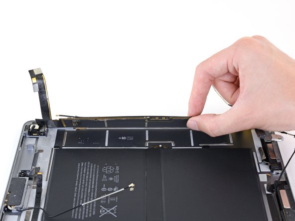
- Apply a few drops of high-concentration isopropyl alcohol under the left edge of the upper logic board arm (Lightning port oriented down).
- Wait thirty seconds for the isopropyl alcohol to weaken the adhesive under the upper logic board arm.
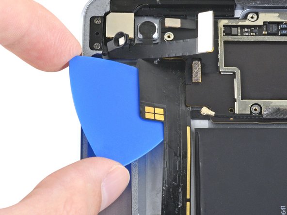
- Use an opening pick to cut through the adhesive under the upper logic board arm and detach it from the frame.
- The upper logic board arm is thin. Be careful not to tear it during this process.
- It may help to grip the upper logic board arm with your fingers and peel it away from the frame.
- Apply a few more drops of isopropyl alcohol under the logic board arm when it becomes difficult to detach from the frame.
- Insert an opening pick about 0.5 inches (13 mm) under the top edge of the larger portion of the upper logic board arm.
- Leave the opening pick under the upper logic board arm to prevent it from re-adhering to the frame.
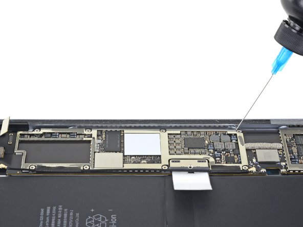
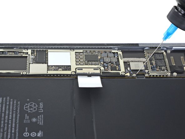
- Apply a few drops of high-concentration isopropyl alcohol to the right edge of the logic board.
- Apply a few drops of high-concentration isopropyl alcohol to the left edge of the logic board.
- Wait one minute for the isopropyl alcohol to weaken the adhesive under the logic board.
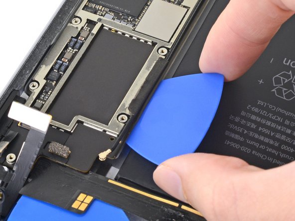
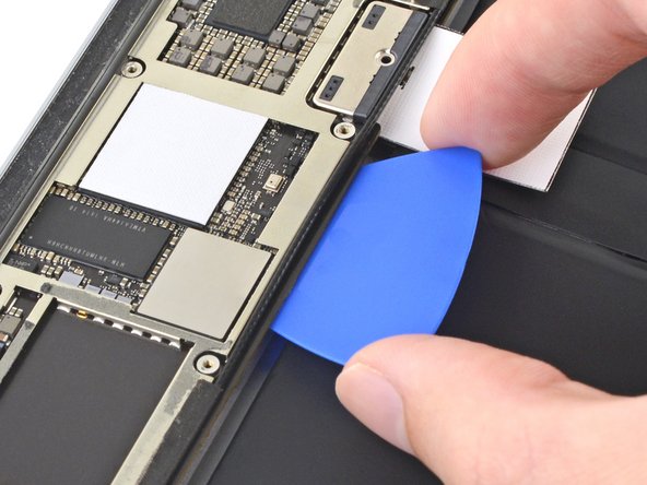
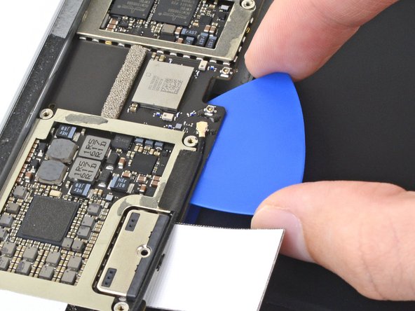
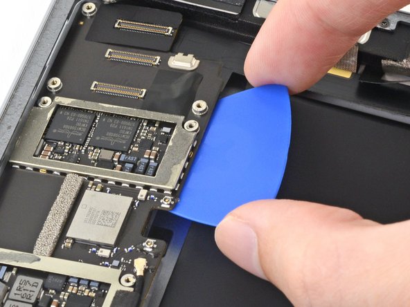
- Slide an opening pick about 0.5 inches (13 mm) under the top of the logic board's left side to cut through the adhesive.
- Remove the opening pick.
- Slide the opening pick about 0.5 inches (13 mm) under the logic board's left side next to the battery connector.
- Remove the opening pick.
- Slide the opening pick about 0.5 inches (13 mm) under the logic board on the other side of the battery connector.
- Remove the opening pick.
- Slide the opening pick about 0.5 inches (13 mm) under the bottom of the logic board's left side.
- Remove the opening pick.
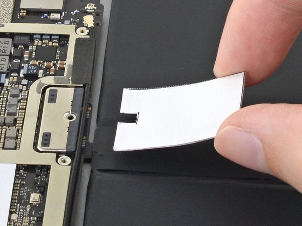
- Remove the battery blocker from the logic board.
- During reassembly, reinsert the battery blocker after you install the logic board into the device.
- Remove the opening pick from the upper logic board arm.
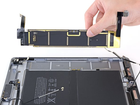
- Remove the logic board from the frame.
- If the logic board doesn't easily lift out of the frame, apply a few more drops of isopropyl alcohol to any stuck areas and use an opening pick to cut through more of the adhesive.
- If there's any alcohol solution remaining in the device, carefully wipe it off or allow it to air dry before installing your logic board.
- During reassembly, follow this guide if you are using a pre-cut adhesive card to secure the logic board to the frame.