PlayStation 3 Potential YLOD Fix
ID: 146948
Description: Video Source-Shawn Shakir on YouTube Check them...
Steps:
- Use the tip of a spudger to remove the black rubber screw cover from the side of the PS3.
- The screw cover may be underneath a warranty sticker. This sticker will change appearance, and show "VOID" after it has been removed.
- Remove the single 8.5 mm T10 Security Torx screw from the smart plate.
- Pull the smart plate toward the hard drive bay, then lift it off the body of the PS3.
- Be sure to keep track of the small metal bracket loosely held in the top cover, if equipped.
- Remove the following seven screws:
- Six 52 mm Phillips screws
- One 30 mm Phillips screw
- Lift the top cover from its rear edge and rotate it toward the front of the PS3.
- Remove the top cover.
- There is a plastic hook located in a hole on the top back right hand side corner. Carefully push the plastic hook a bit from the rear of the machine with a spudger to release the rear right of the casing.
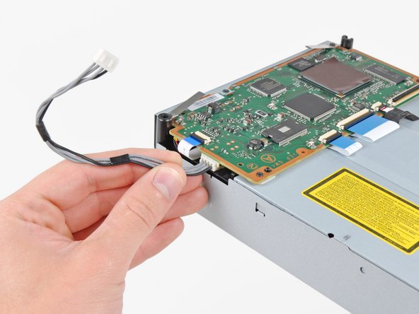
- Disconnect the Blu-ray power cable from the motherboard.
- Pull the connector straight up and out of its socket.
- Lift the Blu-ray drive from the edge nearest the power supply and rotate it away from the chassis enough to access its ribbon cable.
- Use your fingernail to flip up the retaining flap on the Blu-ray ribbon cable socket.
- Be sure you are prying up on the retaining flap, not the socket itself.
- Pull the ribbon cable out of its socket.
- Remove the Blu-ray drive from the PS3.
- If replacing the Blu-ray drive, transfer the power cable to your new drive.
- Pull the control board ribbon cable straight up and out of its socket on the motherboard.
- Remove the two 12 mm Phillips screws securing the control board to the lower case.
- Remove the control board and its attached cable from the PS3.
- Remove the following eight screws securing the motherboard assembly to the lower case:
- Seven 12 mm Phillips screws (ph2)
- One 30 mm Phillips screw
- Remove the control board bracket.
- Use the flat end of a spudger to pry the hard drive bay cover away from the lower case.
- Remove the hard drive bay cover.
- Lift the motherboard assembly out of the lower case.
- Remove the 7.7 mm Phillips screw securing the ground strap to the chassis.
- Pull the AC-In cables slightly away from the rear cover for clearance to access the AC-In connector.
- While depressing its locking mechanism, pull the AC-In connector out of its socket on the power supply.
- Pull the AC inlet out from the bottom of the rear cover, minding any of its cables that may get caught.
- While lightly pulling the rear cover away from the logic board assembly, use the flat end of a spudger to release the clips along the top and bottom edges of the rear cover.
- Remove the rear cover from the logic board assembly.
- De-route the fan cables from the plastic finger molded into the heat sink.
- Disconnect the fan from the motherboard.
- Pull the connector straight up and out of its socket.
- Remove the two 9 mm Phillips screws securing the memory card reader to the chassis.
- Lift the memory card reader out of the PS3 enough to access its ribbon cable.
- Flip up the retaining flap on the memory card reader ribbon cable socket.
- Be sure you are prying up on the retaining flap, not the socket itself.
- Pull the ribbon cable out of its socket and remove the memory card reader.
- Disconnect the DC-In cables from the front of the heat sink.
- Pull the connector toward the front of the PS3.
- Remove the five 9 mm Phillips screws securing the power supply to the chassis.
- Lift the power supply by its front edge to clear the two posts attached to the motherboard.
- Remove the power supply.
- Remove the four 16.5 mm shouldered Phillips screws securing the heat sink to the motherboard.
- Remove the two brackets held under the screws you just removed.
- Lift the motherboard assembly off the heat sink.
- The heat sink may still be held in place by the thermal paste. If this is the case, gently pry the heat sink away from the motherboard housing. Make sure to not bend the copper piping on the heat sink.
- Be sure to apply a new layer of thermal paste when reattaching the heat sink.
- Never applied thermal paste before? Our thermal paste guide makes it easy.
- If you're following the YLOD repair guide, stay tuned for where to apply the replacement thermal paste.
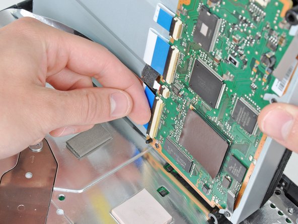
- Flip up the retaining flap on the Blu-ray ribbon cable socket.
- Be sure you are prying up on the retaining flap, not the socket itself.
- Remove the Blu-ray ribbon cable.
- Flip up the flap on the memory card reader ribbon cable socket and remove the ribbon cable.
- Flip up the retaining flap on the Wi-Fi/Bluetooth ribbon cable socket.
- Pull the Wi-Fi/Bluetooth ribbon cable out of its socket.
- Disconnect the DC-In cable from the motherboard and set it aside.
- Pull the connector straight up and out of its socket on the motherboard.
- Disconnect the PRAM battery from the motherboard.
- The PRAM socket is delicate and has the potential to break off the motherboard. If possible, hold down the socket as you disconnect the PRAM battery cable.
- Rotate the PRAM battery slightly counter-clockwise and remove it from the motherboard assembly.
- Remove the blue 8 mm Phillips screw securing the hard drive cage to the chassis.
- Push the hard drive cage toward the front of the motherboard assembly.
- Remove the hard drive from the motherboard assembly.
- Remove the two 3.7 mm #0 Phillips screws securing the chassis to the hard drive socket.
- Remove the two 8.3 mm #0 Phillips screws securing the two halves of the motherboard together.
- Carefully feed the Wi-Fi/Bluetooth ribbon cable through the hole in the top motherboard cover.
- Remove the top motherboard cover.
- Remove the motherboard from the bottom motherboard cover.
- Flip up the retaining flap on the Wi-Fi/Bluetooth ribbon cable socket.
- Remove the Wi-Fi/Bluetooth ribbon cable from the motherboard.
- Motherboard remains.
- Locate the NEC/TOKIN capacitors on your motherboard.
- Choose one capacitor to start with.
- Pry the plastic top off of the capacitor using a metal spudger.
- Remove the rest of the capacitor remnants.
- Clean up the area with Rubbing Alcohol and a toothbrush/cotton bud (or similar).
- Tin the pads with a small amount of solder.
- Place the new capacitors at a small angle, making sure to place the capacitors the right way around.
- The outer rail is the positive side.
- Heat the soldering iron up and tin the tip.
- Solder one side of the capacitor, then solder the other side.
- Solder the other 3 capacitors onto the PS3 motherboard.
- Repeat this process for the other 7 NEC/TOKIN capacitors on the PS3 motherboard.