Ring Glass Break Sensor Teardown
ID: 149082
Description: A look inside the Ring Glass Break Sensor.
Steps:
- Features:
- Glass Break Detector
- Real-Time Notifications
- Simple Setup and Simple App Connection
- Uses three replaceable AA Batteries
- In the Box
- Glass Detect Unit, User and informational Manuals
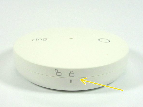
- Close up look at the Glass Break Sensor
- Glass Break Sensor Microphone
- Setup Button
- Twist off bottom for access to the AA batteries
- Pull Tab to enable the batteries to power the sensor
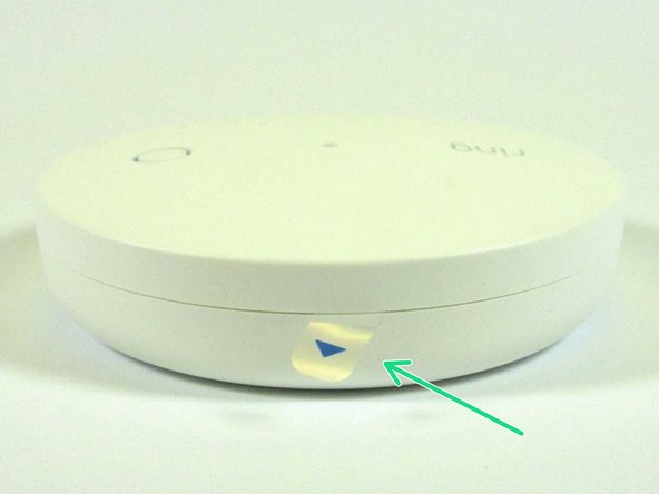
- Backside view of the ring Glass Break Sensor Enclosure
- Double sided tape used for installation of the sensor
- Mounting Holes are also available for on the backside/bottom of the sensor
- Twisting off the bottom of the unit shows the removeable batteries.
- It is nice to see a security product with easily accessible and replaceable batteries
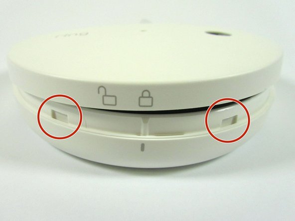
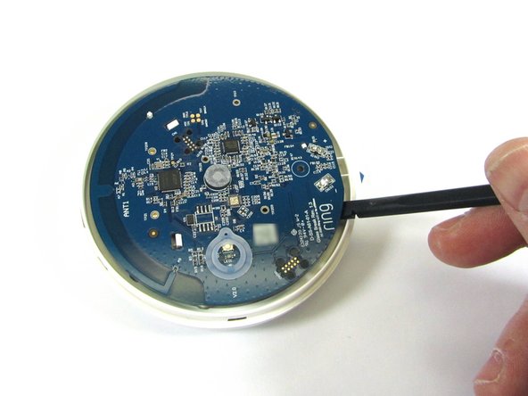
- Next, separate the top with a iFixit Opening Tool to get access to the electronics inside.
- There are number of catches around the outside of the device. These catches popped loose fairly easily with the iFixit Opening Tool.
- Once the top is removed, we get our first look at the internal PCB
- There is a single Philips #0 screw holding the PCB to the enclosure.
- Remove the single screw allows the Internal PCB to be pried out with a Spudger tool
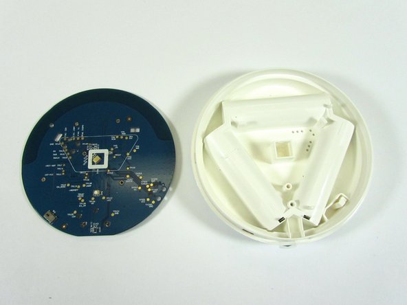
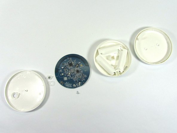
- Internal PCB removed from the enclosure
- Close up view of the back side of the battery compartment that also supports the internal PCB
- Power from the batteries is passed to the PCB via metal tabs
- Tab on the enclosure interfaces to the slide switch on the PCB to cut power when the bottom of the enclosure is rotated to access the batteries
- Battery Mating Connectors for the battery compartment metal tabs . The non-forced connectors allow for easy removal of the PCB from the enclosure
- With the internal PCB removed, we get our first look at the backside and front sides of the PCB.
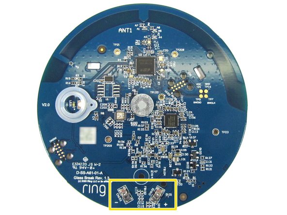
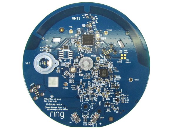
- Close up view of the backside of the PCB
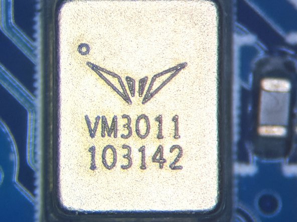
- MEMS Microphone, Vesper VM3011 - World's First Adaptive ZEROPOWER Listening™ Digital Piezoelectric MEMS Microphone
- Close up view of the MEMS Microphone
- Switch/button operation is not documented
- Power Shutoff Switch. When the bottom is rotated to access the batteries - this switch slides as the enclosure bottom is rotated to shutoff battery power to the PCB
- Close up view of the front side of the PCB
- Setup button and environment protection gasket
- Dust filter and protection cover for microphone port
- Close up view of some of the electrical components on the top side of the PCB. Other than the two large ICs on the topside of the PCB, the other components look to be related to power management and control
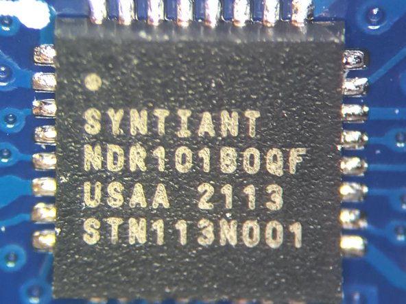
- Syntiant, NDR101BQQF. Always-on Neural Processor. Used for detecting the breaking glass
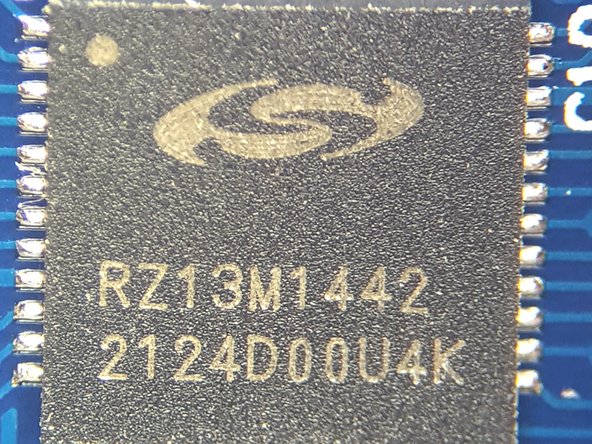
- Silicon Labs, RZ13M1442. Z-Wave Long Range Radio with ARM MCU
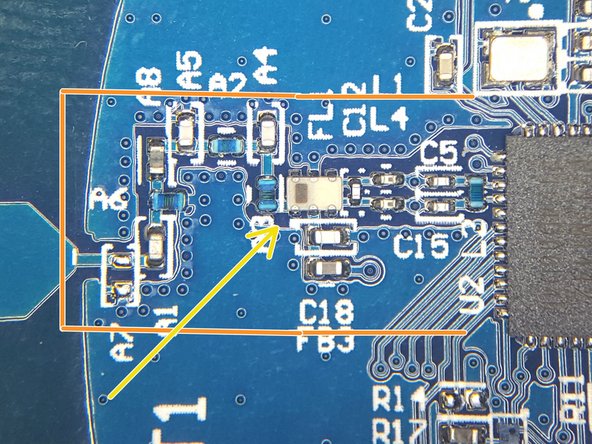
- Close up view of the Glass Break Sensor Antenna and Antenna matching network
- Based on the Antenna Design, the radio is probably sub-GHz
- Antenna Matching Network
- Bandpass SAW Filter
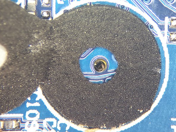
- Close up view of the MEMS Microphone Port
- Acoustic Foam surrounds the Microphone port, and the acoustic foam is capped off with a dust cover
- Teardown Exploded Views of the ring Glass Break Sensor