Dell XPS 15 9550 Motherboard Replacement
ID: 149208
Description: Motherboards are usually the last thing to...
Steps:
- Turn the laptop upside down.
- Make sure the laptop is turned off.
- Use a T5 Torx Screwdriver to remove the ten 3 mm long screws from the perimeter of the back of the laptop.
- Open up the information panel door (on the middle of the back side).
- While holding the door open, use a Phillips #00 Screwdriver to remove the two 10 mm long screws.
- Carefully lift the 2 corners of the back panel close to the hinge upwards, to release the whole panel.
- Do not force the panel off. If it does not come off easily, try to use a plastic spudger where it is stuck.
- There are 2 separate RAM sticks.
- Gently push down on the 2 outside tabs of the RAM stick you want to replace.
- While still pushing down, gently push the tabs outwards, causing the RAM stick to flip up.
- Firmly grasp the RAM stick from the flipped up edge and gently pull out, to release the RAM stick.
- With a Philips #00 Screwdriver bit, remove one 4 mm long black screw located by the antenna connections on the wireless card.
- Set the screw and metal holder aside.
- Gently lift up each of the antennas (3) to disconnect them from the wireless card.
- These are similar to a coat button, the antennas snap on and snap off.
- With the antennas disconnected, gently pull the wireless card out at the angle it sits at.
- The wireless card has been successfully removed!
- Use the Small Plastic Spudger to carefully disconnect the white connector from the black port.
- Use the Phillips #00 Screwdriver to remove the two 4 mm long screws.
- The location of the 2 screws is different on each fan.
- The left fan screw locations are circled in red.
- The right fan screw locations are circled in orange.
- With the screws removed, lift up on the fan and remove it from the laptop.
- Use a Philips #00 Screwdriver to remove the seven 3 mm long screws from the perimeter of the battery.
- Each screw is labeled "M2X4" with an arrow pointing to the screw.
- Gently lift up on the backside of the battery.
- Firmly grasp the black connector on both sides.
- Carefully pull the connector towards the battery, to release the connector and the battery from the laptop.
- The touchpad has two ZIF connectors at the bottom of the motherboard. Use a flat plastic tool to lift the tabs (see picture 2) and gently pull the ribbon cables free.
- When re-assembling, make sure the connectors are set straight and square before closing the tabs.
- Pull this Monitor connector out by its plastic edges
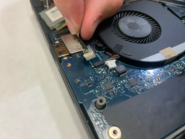
- Remove the single Phillips screw to take off this plate and reveal the connector underneath.
- Pull up the black strap with the plastic spudger, and use your fingers to gently but firmly pull straight up.
- Pull up on the plastic edges to remove the indicated connector at the bottom right of the motherboard.
- This connector in the top left might be taped in two places. Simply pull up to loosen the tape, and use the plastic edges of the connector to pull it out. Have some tape on hand for reassembly, as the tape might have lost its adhesive backing.
- With all mounted components removed, unscrew the motherboard Phillips-head screws.