Dell Chromebook 5190 Motherboard Replacement
ID: 149215
Description: The Dell Chromebook 5190 was released alongside...
Steps:
- Before starting, please make sure you have disconnected and removed all devices populating the laptop's ports.
- Remove the nine M2.5x7.5 screws located on the bottom side of the laptop.
- Be cautious, the following instructions are to prevent cracking the base cover.
- With the opening tool, pry open the upper left corner by the laptop hinge.
- With the opening tool, pry open the upper right corner by the laptop hinge.
- Lift off base cover.
- Unscrew and remove the M2x3 screw holding the silver metal brackets labeled "Battery Bracket" located on the top left side of the battery.
- Unscrew and remove the M2x3 screw holding the silver metal brackets labeled "Battery Bracket" located on the top right side of the battery.
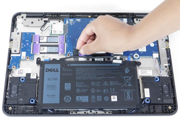
- Remove the clear adhesive tape on the system board from the battery cable from where it's seated above the battery.
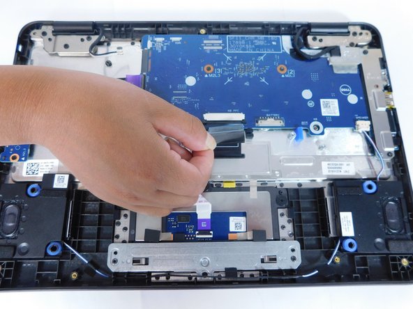
- Pull out the keyboard cable toward you to disconnect it.
- Remove the black adhesive tape on the system board from the battery cable.
- Dismount the cable from where it's seated above the battery.
- Unscrew and remove the four M2x3 screws on each corner of the battery.
- Dismount the battery.
- To disconnect the first purple I/O cable, first lift the purple tab upwards.
- Next, pull the purple tab away from the motherboard.
- To disconnect the second purple I/O cable, first lift the purple tab upwards.
- Next, pull the purple tab away from the motherboard.
- To disconnect the touchpad cable, first lift the purple tab upwards.
- Next, pull the purple tab away from the motherboard.
- Push downwards on the black tabs located on both side of the motherboard connector.
- Disconnect the keyboard cable.
- Disconnect the speaker cable by pulling it from the motherboard connector.
- Screw the single (M2x4) screw on the eDP bracket.
- Unhook the eDP bracket.
- Lift the eDP bracket off.
- Remove clear adhesive tape off the motherboard connector.
- Lift the black tab located on the display connector.
- Disconnect the display cable from the motherboard connector.
- Remove the adhesive tape from the motherboard.
- Unscrew the single (M2x4) screw from the motherboard bracket.
- Unhook the motherboard bracket.
- Lift the motherboard bracket.
- Unscrew 3 (M2x3) screws on the motherboard.
- Unhook the motherboard by placing it at an angle.
- Lift the motherboard.